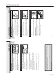
CD Stereo Radio Recorder AZ1009 /00/05/17 AZ1010 /00/01/04/05/10 /11/11H/14/17 xystus DBB DYNAMIC DYNAMIC BASS BASS BOOST BOOST CD S YNCHR O S TA RT REC ORDIN G VOLU VOLUME ME PAUS PAUSE E STOP. STOP.
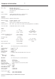
-1 TECHNICAL SPECIFICATION General: Mains voltage : 220V-230V / 50Hz for /00 /04 /14 230V-240V / 50Hz for /05 /10 110V-127V / 220V-240V /50Hz switchable for /01 /11 /11H 120V / 60Hz for /17 Battery : 9V ( 6xR20 ) Power consumption : ≤ 15W at maximum output power, ( ≤ 11W at 1/8 Pmax ) ≤ 5W (typ.
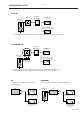
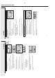
2-2 MEASUREMENT SETUP Tuner FM DUT Bandpass 250Hz-15kHz LF Voltmeter e.g. 7122 707 48001 RF Generator e.g. PM2534 Ri=50Ω e.g. PM5326 S/N and distortion meter e.g. Sound Technology ST1700B Use a bandpass filter to eliminate hum (50Hz, 100Hz) and disturbance from the pilottone (19kHz, 38kHz). Tuner AM (MW,LW) Bandpass 250Hz-15kHz DUT e.g. 7122 707 48001 LF Voltmeter e.g. PM2534 RF Generator e.g. PM5326 S/N and distortion meter Ri=50Ω e.g. Sound Technology ST1700B Frame aerial e.g.
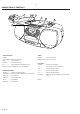
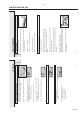
2-3 CONNECTIONS & CONTROLS 3 4 2 1 8 7 6 DB DYN B AMIC BAS S BOO ST CD SY NCHRO VOLU ME PAUS E STOP .OPEN S TA R T RECOR DING FM AM 108 1700 104 1300 104 1000 90 800 OPEN SEARC 92 630 H 5 PLAY 88 TUNING 530 RECORD CD MODE B AS S RE FLEX SPEA KER SYST BASIC FUNCTIONS 1 POWER: CD, TAPE, BAND....selects the sound source EM RADIO 6 TUNING ................tunes to radio stations 1 BAND: FM, MW ...selects the wave band 2 DBB.......................
Batteries (optional) 5 To disconnect the set from the mains completely, remove the mains plug from the wall socket. Your set consists of materials which can be recycled if disassembled by a specialized company. Please observe the local regulations regarding the disposal of packing materials, exhausted batteries and old equipment. All redundant packing material has been omitted.
CS 49 106 If you press 2; and there is no CD inserted, the display shows no. If you make a mistake when operating the CD player, or if the CD player cannot read the CD, the display shows E or no. (See ”TROUBLESHOOTING”.) Note: CD play will also stop if: – you open the CD compartment, – the end of the CD is reached, or – you move the POWER slider. You can interrupt CD play by pressing 2;. Continue CD play by pressing the button again. ™ Display indication: the current track number (flashing).
Note: The program will also be erased if you: – interrupt the power supply, – open the CD compartment, or – move the POWER slider. From the stop position, press 9. ™ no lights up briefly, PROGRAM disappears and your program is erased. Erasing the program Press 2; to play the program. Playing the program If you try to store more than 20 tracks, the display shows F. 4 You can review your settings by pressing and holding CD MODE for more than 1 second.
CS 49 108 6 To stop recording, press STOP·OPEN 9 /. 5 For brief interruptions press PAUSE ;. To resume recording press the PAUSE ; key again. 4 Press RECORD 0 to start recording. 3 Insert a blank, unprotected, cassette and close the cassette compartment. 2 Press STOP·OPEN 9 / to open the cassette compartment. 1 Tune to the desired radio station (see ”RADIO”).
2-8 WARNINGS & SAFETY ESD © WARNING All ICs and many other semiconductors are susceptible to electrostatic discharges (ESD). Careless handling during repair can reduce life drastically. When repairing, make sure that you are connected with the same potential as the mass of the set via a wristband with resistance. Keep components and tools at this potential. f ATTENTION Tous les IC et beaucoup d´autres semi-conducteurs sont sensibles aux décharges statiques (ESD).
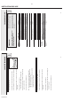
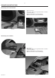
3-1 DISMANTLING INSTRUCTIONS Dismantling of the Cassette Door • Open cassette door. • Release left catch by pressing it inwards with a screwdriver as shown in picture 1. • Pull door on left side up as shown in picture 2. • Right catch will now be released automatically. picture 1 picture 2 Dismantling of the CD Door • Open CD door. • Release left catch by pressing it inwards with a screwdriver as shown in picture 3. • Pull door on left side up as shown in picture 4.
3-2 DISMANTLING INSTRUCTIONS Dismantling the Top Cabinet • Loosen 6 screws as shown in picture 5. • Remove handle by pulling it backwards. picture 5 • Pull volume knob off. • Pull Top cabinet on rear side up first. • Move it backwards to release lugs on front side. • Pull Top cabinet up. Attention: Take care of flex wire to CD drive! picture 6 • Put top cabinet in rest position as shown in picture 7.
3-3 DISMANTLING INSTRUCTIONS Dismantling of the Tape Transport • • • • • Dismantle top cabinet as described page before. Remove cassette door as described in chapter 3-1. Loosen 4 screws as shown in picture 8. Put ornamental cover away. Fetch tape transport through cassette compartment out as shown in picture 9. For service position see chapter SERVICE HINTS. picture 8 picture 9 Separation Front - Rear Cabinet picture 10 • Loosen 9 screws as shown in picture 10.
3-4 SERVICE HINTS SERVICE TOOLS TORX T10 screwdriver with shaftlength 150mm ......................................4822 395 50423 TORX screwdriver set SBC 163 ..............................................................4822 295 50145 Audio signal disc SBC 429......................................................................4822 397 30184 Playability test disc SBC444 ...................................................................
3-5 SERVICE HINTS General Service position For repairs on: CD failures Rec/Pb-amplifier Power-amplifier Power supply Tuner Board picture 12 Service position Tape Transport For repairs on the Tape Transport or for adjustment of the tape speed: • Dismantle tape transport as described in chapter 3-3. • Fix tape transport on cabinet with one screw as shown in picture 13. • Connect cables on Combi Board again.
3-6 SERVICE HINTS Alignment of AZIMUTH • Remove casstte door as described in chapter 3-1. • Insert testcassette SBC420 (4822 397 30071) directly into cassette compartment and play 10kHz part. • Adjust right hand screw for max. output and left channel = right channel.
3-7 CD STARTUP PROCEDURE CD switched on (mode switch) BEGIN +A(CD) supplied to CD part? Remark: To check focus servo, slide servo, track servo and turntable use service test program N - Battery empty? - check +A, - mode switch o.k.? Y Decoder delivers CLOCK frequ. 4.23MHz to µP. µP-RESET line → high µP init. Decoder 7801. Level on pin23 LOW check: - +A(CD), +B(CD), +LASER, +M, - time constant of reset circuit - Pin 32 of µP 7800 HIGH ? - Pin 30 of µP 7800, if 4.23 MHz o.k.
Pin-descriptions of CD ICs SERVO PROCESSOR M62475FP Pin Name Direction 1-3 4-5 6 7 8 9 10 11 12 13 14 15 16 17 18 19 20 21 22 23 24 25 26 27 28 29 30 31 32 33 34 35 36 37 38 39 40 41 42 A, B, C E, F SGT TE TEGain TG1 TE out TC/Shock TS + TG2 TS TS out SS + SS Slide out DET.FILTER BIAS GND MLA/DIS JP1/SG MCK MSD Dout CLPF IREF VCC FSOUT FS FEGain FE SGF CFSR ALPC + ALPC ALPC OUT MRC HF HFI ABC Diode array → Servo processor Diode array → Servo processor Servo processor → Track error ampl.
3-9 NOTES CS 49 118
3-10 SERVICE SERVICETESTPROGRAM TESTPROGRAM 3-10 To enter Service Testprogramm hold PLAY & STOP buttons depressed while switching CD mode on. * To leave Service Testprogram switch CD mode off. * Door switch is ignored → CD door can be opened. Display shows version number of the µ P - software. Slide servo, Radial servo, Focus servo, Disc motor and Laser are switched off. Mute is switched on via decoder IC.
BLOCK DIAGRAM 4-1 4-1 1820 FRONT BOARD 28 29 27 FM Mixer FM frontend FM Det. IF2 IF1 Stereo Decoder FM Osc. VStabB 5 +A(Tuner) AM Osc. +M to/from source switch +A(Tuner) 3 5V AFC AM Det.
5-1 5-1 WIRING DIAGRAM CD DRIVE CD94V5T1 (top view) DETAIL CD-DRIVE: connection of metal frame to ground TOP VIEW BOTTOM VIEW BATTERY COMPARTMENT 6 x 1.5V (R20) GND TELESCOPIC ANTENNA DOOR SWITCH +Batt.
6-1 5 6 7 2 FM-IF2 FM IF1 out AM IF2 V Stab A 1.4V 10 in out 1.4V 12 1V 0.7V 9 FM IF 1 1V 0.7V 7 1.4V 8 V Stab B IF GND 1u P 0.6V 3 0.6V 2 nc 7101 Vcc 7.4V 8.1V TEA5711T MATRIX PHASE DET AM/FM INDIC. SYNCH DET. SOFT MUTE 3107 33R T113 TUNER-L 4 GND T111 3 TUNER_R T110 8.2V 9V 2 +A(TUNER) 1 +A(FM) B T120 SDS CONTROL D V/I CONV. STABILIZER 26 27 1V 1.1V 28 0.7V 29 1.2V 30 0V 32 0.
6-2 B A B A A A 2 4 4 1 2 2 2104 2105 2106 2108 2109 2110 A A A A A B 2111 2112 2113 2114 2115 2116 2 2 3 2 3 3 B B B B A B 3 1 2 1 1 4 2117 2118 2119 2120 2121 2122 A A B B B B 4 4 4 1 1 1 1 2123 3101 3102 3104 3106 3107 A B A B B B 2 4 4 1 1 4 3109 3110 3113 3114 5101 5102 A A B A A B 4 4 1 4 2 4 2 5104 5105 5106 5107a 5107b 5107c B B A A A B 2 3 1 1 1 1 5108 6101 6102 7101 7102 8100 A A A A A A 3 1 1 1 2 4 1 TUNER ADJUSTMENT TABLE 9101 B 2 9150 A 1 9151 B 3 Waverange Input Fr
7-1 4 DISCDISC+ GND INN.SW SLIDE+ SLIDE3828 DOOR SW 2822 9829 3829 3826 3856 3827 GND 3822 3851 3819 3820 2814 3821 3880 3839 2844 2833 9811 2831 3842 2801 2825 D 3825 3882 3844 3800 9816 3849 2835 2876 38 3 383 8 2 3884 3841 9815 3886 3837 2830 HF 34 2871 µP 7800 3802 3847 3814 3871 3870 3848 2858 9819 2873 2874 HF C 3810 3809 1 9802 9807 2638 3644 3812 9851 4.
7-2 13 14 2,5Vpp 9 R61 SEG13 DATA 10 R62 SEG14 I/O PORT 4,4V T2 R81 17 INT2 R80 16 XOUTS R73 15 XINS R72 14 R90 SI 25 R83 T1 24 R82 INT1 ZIN 23 18 19 20 21 22 100p 2835 3881 22k 1 4,4V to RESET CIRCUIT 9,4V T811 JP1/ADJ T812 error_flag +B(CD) T815 T816 4n7 2852 11k 2836 PW 4n7 2851 2880 F 1n PW CRCF 25 SUBCODE DEMOD. DVDD SUBCODE Q REG.
7-3 7-3 4 5 3638 27k 3310 1k8 22n 4n7 2636 15 4,7V 47u 3 2 1626 1 AM TU_R B Rec 220p 2200u 2314 0.47u 2313 0.47u 2310 220p 2309 47u 2307 50K 2315 1N4148 6300 100u 50K 2317 10n 2302 3304 1k5 0u22 2304 3301 2k2 3315 10k 10n 2301 3303 1k5 2303 0u22 1n 3639 10k 220p 2633 3311 1k8 3 TU_L AM left 4Ω G 3553 6k8 PW +A(CD) CD TAPE/OFF 19 FM 6256 10,7V +A 20 J 18 17 AM 16 K 3631 330R 4 x 1N4002 6253 3 220-240V 1 2 110-127V 0.
7-4 4 DISCDISC+ GND INN.SW SLIDE+ SLIDE3828 DOOR SW 2822 9829 3829 3826 3856 3827 3839 2844 9811 2831 3842 2801 2825 D 3825 3882 3844 3800 9816 3849 2835 2876 38 3 383 8 2 3837 2830 2833 9815 3886 2874 µP 34 2871 3812 9851 HF 7800 C 3810 3809 1 3802 3847 3814 3871 3870 3848 2858 9819 3890 2873 3804 3803 9807 2638 3644 GND 3822 3851 3819 3820 2814 3821 3880 9802 3834 2839 3884 3841 HF 4.
8-1 8-1 EXPLODED VIEW / DRAWING 1 MECHANICAL PARTS ––––––––––––––––––––––––––––––––––––––––––––––––––––– 401 4822 410 11403 KEY-SET, TAPE TRANSPORT 402 4822 691 10612 TAPE TRANSPORT, CDS-83VBF-77 403 4822 529 10322 DAMPER, DOOR 404 4822 492 42709 SPRING, OPEN CASSETTE DOOR 406 4822 443 10832 CASSETTE DOOR ASSY, BLACK 406 407 408 409 411 4822 443 10831 4822 410 11404 4822 410 11406 4822 410 11405 4822 492 11061 Pl. Torx 3x10 (2x) DBB 409 Pl. Torx 3x25 (2x) 416 Pl. Torx 3x25 MODE 417 (2x) Pl.
8-2 EXPLODED VIEW / DRAWING 2 426 427 437 526 Pl. Torx 3x10 (3x) 428 527 429 528 403 431 432 DOOR SWITCH 1807 M2x6 (2x) Pl. Torx 2,6x10 (2x) 529 CD DRIVE CD94-V5-T1 433 MECHANICAL PARTS –––––––––––––––––––––––––––––––––––––––––––––––––––– 403 4822 529 10322 DAMPER, DOOR 426 4822 443 10833 CD DOOR, BLACK 426 4822 443 10819 CD DOOR, SILVER 427 4822 532 12798 CD CLAMP 428 4822 535 60096 DAMPING DISC CD 434 (2x) 436 (2x) EVA-EV top, 031097 Pl. Torx 2,6x10 (4x) distinguishing mark pos.
8-3 EXPLODED VIEW TAPE TRANSPORT Only those parts of which a service code number is stated are normal service parts.
9-1 ELECTRICAL PARTSLIST MECHANICAL PARTS ––––––––––––––––––––––––––––––––––––––––––––––––––––– 0001 4822 256 90463 HOLDER FERRITE BAR MISCELLANEOUS ––––––––––––––––––––––––––––––––––––––––––––––––––––– 1250 4822 277 11739 SWITCH SLIDE, MODE 1302 4822 267 31468 SOCKET HEADPHONE 3,5mm Jack 1350 4822 276 12648 SWITCH PUSH, DBB 1626 4822 277 11504 SWITCH SLIDE, REC/PB 1800 4822 276 13114 TACT SWITCH 1801 1802 1803 1804 1807 4822 276 13114 4822 276 13114 4822 276 13114 4822 276 13114 4822 276 12889 TACT SWIT
9-2 ELECTRICAL PARTSLIST CAPACITORS ––––––––––––––––––––––––––––––––––––––––––––––––––––– 2844 4822 122 33195 100pF 10% 50V 2846 4822 122 33197 1nF 10% 50V 2848 4822 122 33197 1nF 10% 50V 2850 4822 126 12882 100nF 20% 50V 2851 4822 126 11714 4,7nF 20% RESISTORS ––––––––––––––––––––––––––––––––––––––––––––––––––––– 3637 4822 116 52264 27kΩ 5% 0,5W 3638 4822 116 52264 27kΩ 5% 0,5W 3639 4822 116 83864 10kΩ 5% 0,5W 3640 4822 116 83864 10kΩ 5% 0,5W 3641 4822 116 52228 680Ω 5% 0,5W 2852 2854 2855 2856 2859 48
9-3 ELECTRICAL PARTSLIST RESISTORS ––––––––––––––––––––––––––––––––––––––––––––––––––––– 3853 4822 116 52244 15kΩ 5% 0,5W 3854 4822 116 52243 1,5kΩ 5% 0,16W 3855 4822 116 52271 33kΩ 5% 0,16W 3856 4822 116 52303 8,2kΩ 5% 0,5W 3857 4822 116 52269 3,3kΩ 5% 0,5W DIODES ––––––––––––––––––––––––––––––––––––––––––––––––––––– 6252 ! 4822 130 31878 1N4003G 6253 ! 4822 130 31878 1N4003G 6256 4822 130 30621 1N4148 6300 4822 130 30621 1N4148 6625 4822 130 34167 BZX79-B6V2 3858 3859 3860 3861 3862 4822 116 80176 482