BDL4230ET www.philips.
User Manual BDL4230ET SAFETY AND TROUBLESHOOTING INFORMATION Safety precautions and maintenance WARNING: Use of controls, adjustments or procedures other than those specified in this documentation may result in exposure to shock, electrical hazards and/or mechanical hazards. Read and follow these instructions when connecting and using your display: Operation: • Keep the display out of direct sunlight and away from stoves or any other heat sources.
User Manual BDL4230ET Service: • The casing cover should be opened only by qualified service personnel. • If there is any need for repair or integration, please contact your local service center. • Do not leave your display under direct sunlight. If your display does not operate normally, having followed the instructions set out in this document, please contact a technician or your local service center.
User Manual BDL4230ET REGULATORY INFORMATION CE DECLARATION OF CONFORMITY MMD declares under our responsibility that the product is in conformity with the following standards • EN60950-1:2006+A11:2009 (Safety requirement of Information Technology Equipment) • EN55022:2006+A1:2007 (Radio Disturbance requirement of Information Technology Equipment) • EN55024:1998+A1:2001+A2:2003 (Immunity requirement of Information Technology Equipment) • EN61000-3-2:2006 (Limits for Harmonic Current Emission) • EN61000-3-3:
User Manual BDL4230ET POLISH CENTER FOR TESTING AND CERTIFICATION NOTICE The equipment should draw power from a socket with an attached protection circuit (a three-prong socket). All equipment that works together (computers, monitors, printers and so on) should have the same power supply source. The phasing conductor of the room’s electrical installation should have a reserve short-circuit protection device in the form of a fuse with a nominal value no larger than 16 Amperes (A).
User Manual BDL4230ET INFORMATION FOR UK ONLY WARNING - THIS APPLIANCE MUST BE EARTHED. Important: This apparatus is supplied with an approved moulded 13A plug. To change a fuse in this type of plug proceed as follows: 1. Remove fuse cover and fuse. 2. Fit new fuse which should be a BS 1362 5A, A.S.T.A. or BSI approved type. 3. Refit the fuse cover. If the fitted plug is not suitable for your socket outlets, it should be cut off and an appropriate 3-pin plug fitted in its place.
User Manual BDL4230ET Ё⬉ᄤֵᙃѻક∵ᶧࠊ㸼⼎㽕∖ ( Ё RoHS ⊩㾘ᷛ⼎㽕∖ *!ѻકЁ᳝↦᳝ᆇ⠽䋼ܗ㋴ ⱘৡ⿄ঞ䞣 䚼ӊৡ⿄ ⎆䴶ᵓ ⬉䏃ᵓ㒘ӊ 䰘ӊ ( 䘹఼ˈ⬉⑤㒓ˈ䖲㒓 ) 䘹఼⬉∴ ᳝↦᳝ᆇ⠽䋼ܗ㋴ ݁Ӌ䫀 ⒈㘨㣃 䬝 + (PBB) (Cd) (Cr 6 ) O O O O O O O O O 䪙 (Pb) O X X ∲ (Hg) O X O X O O O O O X O O O O O ⒈Ѡ㣃䝮 (PBDE) O O O O˖㸼⼎䆹᳝↦᳝ᆇ⠽䋼䆹䚼ӊ᠔᳝ഛ䋼ᴤ᭭Ёⱘ䞣ഛ SJ/T11363-2006 ᷛޚ㾘ᅮⱘ䰤䞣㽕∖ҹϟDŽ X˖㸼⼎䆹᳝↦᳝ᆇ⠽䋼㟇ᇥ䆹䚼ӊⱘᶤϔഛ䋼ᴤ᭭Ёⱘ䞣䍙ߎ SJ/T11363-2006 ᷛޚ㾘ᅮⱘ䰤䞣㽕∖DŽ ⦃ֱՓ⫼ᳳ䰤 ℸᷛ䆚ᣛᳳ䰤 ( कᑈ )ˈ⬉ᄤֵᙃѻકЁ᳝ⱘ᳝↦᳝ᆇ⠽䋼ܗ㋴ℷᐌՓ⫼ⱘᴵӊϟϡӮথ⫳⊘さবˈ ⬉ᄤֵᙃѻક⫼᠋Փ⫼䆹⬉ᄤֵᙃѻકϡӮᇍ⦃๗䗴៤Ϲ䞡∵ᶧᇍ݊Ҏ䑿ǃ䋶ѻ䗴៤Ϲ䞡ᤳᆇⱘᳳ䰤DŽ ljᑳᓗ⬉఼⬉ᄤѻકಲᬊ
User Manual BDL4230ET NORTH EUROPE (NORDIC COUNTRIES) INFORMATION Placering/Ventilation VARNING: FÖRSÄKRA DIG OM ATT HUVUDBRYTARE OCH UTTAG ÄR LÄTÅTKOMLIGA, NÄR DU STÄLLER DIN UTRUSTNING PÅPLATS. Placering/Ventilation ADVARSEL: SØRG VED PLACERINGEN FOR, AT NETLEDNINGENS STIK OG STIKKONTAKT ER NEMT TILGÆNGELIGE. Paikka/Ilmankierto VAROITUS: SIJOITA LAITE SITEN, ETTÄ VERKKOJOHTO VOIDAAN TARVITTAESSA HELPOSTI IRROTTAA PISTORASIASTA.
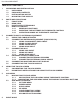
User Manual BDL4230ET TABLE OF CONTENTS 1. UNPACKING AND INSTALLATION 1.1. UNPACKING 1.2. PACKAGE CONTENTS 1.3. INSTALLATION NOTES 1.4. MOUNTING THE DISPLAY 2. PARTS AND FUNCTIONS 2.1. FRONT VIEW 2.2. REAR VIEW 2.3. INPUT/OUTPUT TERMINALS 2.4. REMOTE CONTROL 2.4.1. GENERAL FUNCTIONS 2.4.2. INSERTING THE BATTERIES IN THE REMOTE CONTROL 2.4.3. OPERATING RANGE OF THE REMOTE CONTROL 3. CONNECTIONS TO EXTERNAL EQUIPMENT 3.1. USING THE CABLE RETAINER 3.2. CONNECTING EXTERNAL EQUIPMENT (DVD/VCR/VCD) 3.2.1.
User Manual BDL4230ET 7. PIXEL DEFECT POLICY 7.1. PIXELS AND SUB-PIXELS 7.2. TYPES OF PIXEL DEFECTS + DOT DEFINITION 7.3. BRIGHT DOT DEFECTS 7.4. DARK DOT DEFECTS 7.5. PROXIMITY OF PIXEL DEFECTS 7.6. PIXEL DEFECT TOLERANCES 8. CLEANING AND TROUBLESHOOTING 8.1. CLEANING 8.2. TROUBLESHOOTING 9.
User Manual BDL4230ET 1. UNPACKING AND INSTALLATION 1.1. UNPACKING • This product is packed in a carton, together with the standard accessories. • Any other optional accessories will be packed separately. • Due to the size and weight of this display it is recommended for two people to move it. • The protective glass and glass substrate are installed on the front of the product. Since glass can be both broken and scratched easily, the product should be handled with care.
User Manual BDL4230ET 1.4. MOUNTING THE DISPLAY Wall mounting holes Notes: • M6 (10mm) screws (with a length 10-15mm longer than the thickness of the mounting bracket) are needed for wall mounting (not included). Tighten the screws securely (recommended torque: 470 - 635N cm) • The mounting interface should comply with the UL1678 standard in North America. The mounting means should be strong enough to bear the weight of the display (approx. 28 kg (61.7 lb) without stands).
User Manual BDL4230ET 2. 2.1. PARTS AND FUNCTIONS FRONT VIEW 1 1. Remote control sensor, ambient light sensor and power indicator • Receives command signals from the remote control. • Detects the ambient lighting conditions around the display.
User Manual BDL4230ET REAR VIEW 8 7 100 mm 100 mm 9 Dent depth: 6mm 290.4 mm 100 mm 280 mm 2.2. 35 mm 200 mm 210.4 mm 1 2 3 4 5 6 1. ENTER/VIDEO SOURCE button • Use this button to select the input source. • When the On Screen Display menu is active, this is also used as the SET button. 2. MENU button • Use this button to engage the On Screen Display menu. • When the On Screen Display menu is active, use this button to return to the previous menu. 3.
User Manual BDL4230ET 2.3. INPUT/OUTPUT TERMINALS 17 7 1 2 3 4 5 6 1. AUDIO IN (AUDIO1) Connects to the audio output of a computer. 2. AUDIO OUT R/L Outputs the audio signal from the AUDIO IN (AUDIO1/AUDIO2/AUDIO3) or HDMI jack. 3. SPEAKERS R/L Outputs the audio signal from the AUDIO IN (AUDIO1/AUDIO2/AUDIO3) or HDMI jack to external speakers. 4. AUDIO IN (AUDIO2/AUDIO3) Connects to the audio output of an AV device. 8 12 9 10 11 13 14 15 16 9.
User Manual BDL4230ET 2.4. 2.4.1. REMOTE CONTROL GENERAL FUNCTIONS POWER button Press to switch on the display from standby mode. Press again to turn it to standby mode. SMART button To select smart picture mode from: • HIGHBRIGHT: for moving images such as Video • STANDARD: for images (factory setting) • sRGB: for text based images • CINEMA: for movies. • CUSTOM: create your own picture settings. This mode is automatically selected after you change the settings in the PICTURE menu.
User Manual BDL4230ET BRIGHTNESS button Press to open the BRIGHTNESS OSD selection, and then press the PLUS or MINUS button to adjust the value. DISPLAY button To turn on/off the setting information displayed on the upper right corner of the screen. MENU button To turn the OSD menu on/off. UP button • To move the highlight bar up to adjust the selected item when OSD menu is on. • To move the sub-picture up in “PIP” mode.
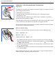
User Manual BDL4230ET 2.4.2. INSERTING THE BATTERIES IN THE REMOTE CONTROL 1. Remove the cover on the rear of the remote control. 2. Insert two AAA size 1.5V batteries ensuring that the “+” and “-” ends of the batteries are correctly aligned. 3. Replace the cover. Note: Do not mix battery types, e.g. alkaline and manganese. 2.4.3. OPERATING RANGE OF THE REMOTE CONTROL When pressing a remote control button, point the top of the remote control towards the remote control sensor.
User Manual BDL4230ET 3. CONNECTIONS TO EXTERNAL EQUIPMENT 3.1. USING THE CABLE RETAINER 3.2. CONNECTING EXTERNAL EQUIPMENT (DVD/VCR/VCD) 3.2.1. USING COMPONENT VIDEO INPUT 1. Connect the green-colored (labeled as "Y") jack of the device to the green-colored "Y" jack of the display. 2. Connect the blue-colored (labeled as "Pb") jack of the device to the blue-colored "Pb" jack of the display. 3. Connect the red-colored (labeled as "Pr") jack of the device to the red-colored "Pr" jack of the display.
User Manual BDL4230ET 3.2.2. USING S-VIDEO INPUT 1. Connect the S-Video connector of the external device to the S-VIDEO input of the display. 2. Connect the red (R) and white (L) audio jacks of the device to the AUDIO IN (AUDIO2 or AUDIO3) jacks of the display. DVD/VCR/VCD 3.2.3. USING VIDEO INPUT 1. Connect the Video connector of the external device to the VIDEO IN input of the display. 2. Connect the red (R) and white (L) audio jacks of the device to the AUDIO IN (AUDIO2 or AUDIO3) jacks of the display.
User Manual BDL4230ET 3.2.4. USING HDMI INPUT Connect the HDMI connector of the external device to the HDMI input of the display. DVD/VCR/VCD 3.3. CONNECTING A PC 3.3.1. USING VGA INPUT 1. Connect the 15-pin VGA connector of the PC to the VGA IN connector of the display. 2. Connect the audio cable to the AUDIO IN (AUDIO1) input of the display.
User Manual BDL4230ET 3.3.2. USING DVI INPUT 1. Connect the DVI-D connector of the PC to the DVI-D connector of the display. 2. Connect the audio cable to the AUDIO IN (AUDIO1) input of the display. PC 3.3.3. USING HDMI INPUT 1. Connect the DVI-D connector of the PC to the HDMI connector of the display using a DVI-HDMI cable. 2. Connect the audio cable to the AUDIO IN (AUDIO1) input of the display.
User Manual BDL4230ET 3.4. EXTERNAL AUDIO CONNECTION 3.4.1. CONNECTING EXTERNAL SPEAKERS 1. Connect the speaker wires to the external speaker (SPEAKERS) output of the display. 2. Turn on the unit. Note: Make sure your display is turned off before connecting the speaker wires. External speaker 3.4.2. CONNECTING EXTERNAL AUDIO DEVICE Connect the red (R) and white (L) audio jacks of the external audio device to the AUDIO OUT R/L jacks of the display.
User Manual BDL4230ET 3.5. CONNECTING ANOTHER BDL4230ET DISPLAY You can interconnect multiple BDL4230ET units to create a daisy-chain configuration for applications such as a video wall. However, if you will be actively using the touch screen application, we do not recommend video wall mounting. Note: The number of displays that can be used in a daisy-chain configuration will depend on the resolution of the input signal being used.
User Manual BDL4230ET 4. USING THE TOUCH SCREEN You can use the optical touch screen to control your operating system. The touch screen can emulate basic mouse functions and supports multi-touch functions for Windows 7*. The following table shows a list of gestures you can use on the touch screen. Note: Ensure that you have installed the USB cable on the display to a PC. * Multi-touch functions are only supported by Windows 7 - Home Premium, Professional, Enterprise and Ultimate versions.
User Manual BDL4230ET OS functions Gesture actions For Windows Vista and Windows 7 Drag one finger left or right. Selection Quickly drag your finger (Flick) in a desired direction. Pan up / Pan down / Back / Forward Multi-touch functions For Windows 7 - Home Premium, Professional, Enterprise and Ultimate versions 1. Press on the target. 2. Tap the screen with another finger. 3. Release the second finger. Right-click Drag one or two fingers up or down.
User Manual BDL4230ET OS functions Gesture actions Move two fingers apart or toward each other. Zoom • Move two fingers in opposing directions. • Use one finger to pivot around another. Supported by specific applications Tap two fingers simultaneously. The target should be the midpoint between the fingers. Supported by specific applications For Windows XP, Windows Vista and Windows 7 Press and hold for 4 seconds.
User Manual BDL4230ET 4.1. CALIBRATING THE TOUCH SCREEN • The function described in this section only applies to Windows 7 - Home Premium, Professional, Enterprise and Ultimate versions. • Ensure that you have installed the USB cable on the display to a PC. You can calibrate the touch screen to use it more efficiently. To adjust calibration: 1. In Windows, tap the Start button and then Control Panel. In the search box, type Tablet PC Settings and tap Tablet PC Settings from the result list. 2.
User Manual BDL4230ET 5. OSD MENU An overall view of the On-Screen Display (OSD) structure is shown below. This can be used as a reference for further adjusting your display. 5.1. 5.1.1. NAVIGATING THE OSD MENU NAVIGATING THE OSD MENU USING THE REMOTE CONTROL 1. Press the MENU button on the remote control to display the OSD menu. 2. Press the UP/DOWN button to choose the item you want to adjust. 3. Press the PLUS/SET button to enter the submenu. 4.
User Manual BDL4230ET 5.1.2. NAVIGATING THE OSD MENU USING THE DISPLAY’S CONTROL BUTTONS 1. Press the MENU button to display the OSD menu. 2. Press the / button to choose the item you want to adjust. 3. Press the ENTER/VIDEO SOURCE button to enter the submenu. 4. In the submenu, press the / button to toggle between items, or press / button to adjust settings. If there is a submenu, press the ENTER/VIDEO SOURCE button to enter it. 5.
User Manual BDL4230ET 5.2. 5.2.1. OSD MENU OVERVIEW PICTURE MENU P IC T UR E BR IGH TNE S S CON TRA ST S HA RP NE S S BL ACK L E V E L NOI S E RE DU CTI ON TI NT COLOR COL OR T EM P E RAT U RE COL OR C O NTR OL L I G H T SE N SO R S MA RT CON TRAS T V ID EO S O UR CE P IC T UR E RE S E T Se l A djus t E nter 10 0 50 5 70 OFF 50 50 10 00 0 K OFF OFF Ba ck Qui t BRIGHTNESS Note: This function is not available when SMART CONTRAST, LIGHT SENSOR or BRIGHTNESS under PANEL SAVING is turned on.
User Manual BDL4230ET COLOR TEMPERATURE Select a color temperature for the image. The image has a reddish tint with a lower color temperature, whilst a higher color temperature gives off a more bluish tint. Use the PLUS/MINUS button to make selection. COLOR CONTROL Note: This function is only available when COLOR TEMPERATURE is set to USER. With this function you can adjust the color tones of the image precisely by changing the R (Red), G (Green) and B (Blue) settings independently.
User Manual BDL4230ET 5.2.2. SCREEN MENU S CR EE N H P O SI T I O N V P O S IT I O N CL OCK CL OCK P HAS E ZOOM M O DE CU STOM ZOO M S CR EE N RE S E T Se l A djus t 50 50 16 14 F ULL E nter Ba ck Qui t H POSITION Notes: • For VGA input only. • This function is not available when TOUCH FEATURE is turned on. Disable TOUCH FEATURE to make this function accessible from the OSD menu. Adjust the horizontal placement of the picture.
User Manual BDL4230ET The pictures you receive may be transmitted in 16:9 format (widescreen) or 4:3 format (conventional screen). 16:9 pictures sometimes have a black band at the top and bottom of the screen (letterbox format). This function allows you to optimize the picture display on screen. The following zoom modes are available: • FULL - This mode restores the correct proportions of pictures transmitted in 16:9 using the full screen display.
User Manual BDL4230ET 5.2.3. AUDIO MENU AU DI O V O L UM E M UT E AU DI O S O UR CE S P EA KE R AU DI O RE S E T Se l A djus t 30 OFF IN TE RNA L E nter Ba ck Qui t VOLUME Adjust to increase or decrease the audio output level. Use the PLUS/MINUS button to adjust. MUTE To turn the mute function on/off. Use the PLUS/MINUS button to make selection. AUDIO SOURCE To select the audio input source according to the source connected to the audio input and HDMI sockets on the display.
User Manual BDL4230ET 5.2.4. PIP MENU Notes: • For COMPONENT, VGA, DVI-D and HDMI inputs only. • For FULL and NORMAL zoom modes only. • The PIP function is turned off by default. Press the PIP ON/OFF button on the remote control to turn on PIP and make it accessible from the OSD menu. • When TOUCH FEATURE is turned on, the PIP function will be disabled. Items under the PIP menu will also become unavailable.
User Manual BDL4230ET 5.2.5. CONFIGURATION 1 MENU CO N F IG U RAT IO N 1 AU TO AD JU ST P O W ER S AV E LA NGUA GE PANE L S AV ING CO L O R S Y S T E M CO N F IG U RAT IO N RE S E T FACTO RY RE S ET Se l A djus t E nter E NG LIS H AU TO Ba ck Qui t AUTO ADJUST Note: For VGA input only. Use this function to automatically optimize the display of the VGA image. Press the SET button to adjust. POWER SAVE Set the display to reduce the power automatically.
User Manual BDL4230ET Note: For VIDEO and S-VIDEO inputs only. Select the color system depending on the input video format. Use the PLUS/MINUS button to toggle between • AUTO • PAL 4.43 • PAL 3.58 • SECAM • NTSC 4.43 • NTSC 3.58 CONFIGURATION RESET Reset all settings in the CONFIGURATION 1 menu. Press the SET/PLUS button to open the submenu, and then press the UP/DOWN button to make selection. Select YES and press the SET button to restore settings to factory preset values.
User Manual BDL4230ET 5.2.6. CONFIGURATION 2 MENU CO N F IG U RAT IO N 2 OSD TUR N OF F OS D MO D E IN FORM ATI O N OS D S L E E P T IM E R O S D H PO S I T I O N O S D V P O S IT I O N M O NITOR IN FORM AT I O N TO UCH FE AT URE Se l A djus t E nter 60 LA NDS C AP E OFF OFF 50 50 ON Ba ck Qui t OSD TURN OFF Set the period of time the OSD menu stays on the screen (from 5 to 120 seconds) Use the PLUS/MINUS button to adjust.
User Manual BDL4230ET 5.2.7. ADVANCED OPTION MENU AD VA NC ED OPTI ON I N P UT RE S OL UT I ON BLACK LEVEL EXPANSION G AM M A S E L E CT IO N S CA N M O DE S CA N C O NV E RS IO N F I L M MO D E IR C O NT R O L KE Y BOA RD CON TROL TI LIN G HE AT S TATU S DATE AN D TIM E S CH ED UL E M O NITO R ID DD C/ CI S MA RT P O WE R AUTO SIGNAL DETECTION ADVANCED OPTION RESET Se l A djus t E nter OFF OFF OFF OFF OFF OFF OFF OFF OFF Ba ck Qui t INPUT RESOLUTION Notes: • For VGA input only.
User Manual BDL4230ET SCAN CONVERSION Note: For VIDEO, S-VIDEO, COMPONENT, and HDMI (video mode) inputs only. Choose to enable or disable the IP (Interlace to Progressive) conversion function. Use the PLUS/MINUS button to toggle between • PROGRESSIVE - Enable the IP conversion function (recommended). Once enabled, the interlace input signal will be converted to progressive format for better display quality. • INTERLACE: Disable the IP function.
User Manual BDL4230ET Example: 2 x 2 screen matrix (4 displays) H MONITORS = 2 V MONITORS = 2 5 x 5 screen matrix (25 displays) H MONITORS = 5 V MONITORS = 5 H MONITORS POSITION POSITION V MONITORS V MONITORS H MONITORS • H MONITORS - Select the number of displays on the horizontal side. • V MONITORS - Select the number of displays on the vertical side. • POSITION - Select the position of this display in the screen matrix.
User Manual BDL4230ET For example, if you wish to turn the display on automatically at 7:30 AM and off at 10:30 PM on Tuesdays and Wednesdays and display the signal from the HDMI input: Time 0:00 1:00 2:00 3:00 4:00 5:00 6:00 7:00 8:00 9:00 10:00 11:0012:0013:0014:0015:0016:0017:0018:0019:0020:0021:0022:0023:00 MON TUE WED Day THU FRI SAT SUN Off Off Off On On Off Off Off Off Off Off Perform the following steps: 1.
User Manual BDL4230ET 11. Press the EXIT button and the menu will close and the schedule settings will take effect. To set up more schedule items, repeat the steps above except that a different schedule item should be selected (schedule item #2 ( 2) through #7 ( 7)) in step 2. Notes: • Seven scheduling options are available so that you can choose between different video input modes for different schedules during the week. For example, VGA input on a Monday, HDMI on Tuesday to Friday, S-VIDEO for weekends.
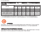
User Manual BDL4230ET 6. INPUT MODE VGA Resolution Standard Resolution Active Resolution H Pixels V Lines Refresh Rate Pixel Rate 60 Hz 25.175 MHz Aspect Ratio Stand for Mode VGA 640 480 72 Hz 75 Hz 31.5 MHz 31.5 MHz 4:3 Video Graphic Array WVGA 720 400 70 Hz 33.75 MHz 16:9 Wide Video Graphic Array SVGA 800 600 Super VGA 1024 768 4:3 Extended Graphic Array WXGA 1280 768 40 MHz 49.5 MHz 65 MHz 78.75 MHz 79.
User Manual BDL4230ET • If a vertical and horizontal frequency-select mode exists, select 60Hz (vertical) and 31.5KHz (horizontal). In some cases, abnormal signals (such as stripes) might appear on the screen when the PC power is turned off (or if the PC is disconnected). If this happens, press the INPUT button to enter the video mode. Also, make sure that the PC is connected. • If horizontal synchronous signals seem irregular in RGB mode, check PC power saving mode or cable connections.
User Manual BDL4230ET 7. PIXEL DEFECT POLICY We strive to deliver the highest quality products and use some of the industry's most advanced manufacturing processes whilst practicing stringent quality control. However, pixel or sub-pixel defects on the PDP / TFT panels used in Plasma- & LCD- displays are sometimes unavoidable.
User Manual BDL4230ET 7.3. BRIGHT DOT DEFECTS Bright dot defects appear as pixels or sub-pixels that are always lit or "on". These are the examples of bright dot defects: One lit red, green or blue sub-pixel Two adjacent lit sub-pixels: - Red + Blue = Purple - Red + Green = Yellow - Green + Blue = Cyan (Light Blue) Three adjacent lit sub-pixels (one white dot) 7.4. DARK DOT DEFECTS Black dot defects appear as pixels or sub-pixels that are always dark or "off".
8. CLEANING AND TROUBLESHOOTING 8.1. CLEANING Caution When Using the Display • Do not place your hands, face or objects close to the ventilation holes of the display. The top of the display is usually very hot due to the high temperature of the air being expelled through the ventilation holes. Burns or personal injuries may occur if any body parts are brought too close. Placing any object near the top of the display could also result in heat related damage to the object as well as the display itself.
User Manual BDL4230ET 8.2. TROUBLESHOOTING Symptom No picture is displayed Possible Cause 1. The power cord is disconnected. 2. The main power switch on the back of the display is not switched on. 3. The selected input has no connection. 4. The display is in standby mode with VGA. Interference displayed on Caused by surrounding electrical the screen or audible noise appliances, traffic or fluorescent lights. is heard Remedy 1. Plug in the power cord. 2. Make sure the power switch is switched on. 3.
User Manual BDL4230ET 9. TECHNICAL SPECIFICATIONS Display Item Screen Size (Active Area) Aspect Ratio Number of Pixels Pixel Pitch Displayable Colors Brightness Smart Contrast Contrast Ratio (Typical) Viewing Angle Specifications 42” (107 cm) LCD 16:9 1920 (H) x 1080 (V) 0.4845 (H) x 0.4845 (V) [mm] 1.
User Manual BDL4230ET Dimension [W x H x D mm] With Stand Without Stand Weight With Stand Without Stand Environmental Condition Item Operational Temperature Storage Operational Humidity Storage Operational Pressure Storage / Shipment 992 x 631 x 405 mm 992 x 585 x 128 mm 30 Kg 28 Kg Specifications 0 ~ 40 C -20 ~ 60 C 20 ~ 80% RH (No condensation) 5 ~ 95% RH (No condensation) 800 ~ 1100 hPa (Altitude: 0 ~ 4,000 m) 700 ~ 1100 hPa (Altitude: 0 ~ 15,000 m) Internal Speaker Item Type Input Impedance Output Sou
User Manual BDL4230ET RETURN TO THE CONTENTS