Industrial Vision Intelligent Camera - Inca 320 12 NC: 8122 410 5693.
Inca 320 Hardware Manual Version 1.0 A publication of: Philips Applied Technologies Industrial Vision www.apptech.philips.com/industrialvision © 2005 Philips Electronics N.V. Eindhoven, The Netherlands All rights are reserved. Reproduction in whole or in part is prohibited without the written consent of the copyright owner. The information in this publication is furnished for guidance, and with no guarantee as to its accuracy or completeness.
CONTENTS Inca 320 Hardware Manual ............................................................................................................................... 2 1 1.1 1.2 1.3 2 2.1 2.2 2.3 2.4 INTRODUCTION ........................................................................................................................................ 3 ABOUT THIS MANUAL............................................................................................................... 3 SUPPLIED PARTS...............
6.2 7 Page 2 SERVICE AND SUPPORT ........................................................................................................20 TECHNICAL SPECIFICATION.................................................................................................................
1 INTRODUCTION Congratulations on buying the Inca vision system! An Inca is a high quality intelligent camera for image acquisition and processing. Inca offers a complete vision system that is ACCURATE, FAST, COMPACT and COSTEFFECTIVE. The high-resolution, high dynamic range sensor provides the best basis for the development of a very accurate vision system.
2 HARDWARE The Inca hardware consists of the following modules: • TriMedia processor • CMOS sensor • Ethernet 10BaseT/100BaseT interface • RS232 serial interface • Video outputs VGA and CVBS • Digital inputs and outputs • Trigger input and flashlight output • Reset input and watchdog output • Four general purpose LEDs • One system LED • 8 MByte on-board flash memory • 32 MByte SDRAM Page 4 2.1 TRIMEDIA PROCESSOR The core of the Inca is the TriMedia 1300 processor.
2.2 2.2.1 CMOS SENSOR Inca 320 In the Inca 320 a monochrome sensor IBIS5A-1300 from FillFactory is implemented. This sensor is dedicated to industrial machine vision solutions and has both a rolling and a synchronous shutter. High dynamical range scenes can be captured using the double or multiples slope functionality.
2.3.1 10BaseT/100BaseT For the interconnection of the Inca camera to the host PC a so-called 10BaseT (for 10Mbs) or 100BaseT (for 100Mbs) connection is used, which is a twisted pair connection for Ethernet. For this link the PC must be equipped with an Ethernet Controller. In order to be able to control multiple Inca 320 cameras a decent knowledge of how an Ethernet network has to be configured is required. This manual assumes the reader has this knowledge. immediate when the trigger input is signaled.
is configured as a non-inverting output the output is zero and stays zero and awaits control by the software. If the output is configured as an inverting output than during the start-up sequence the output equals the value of the power supply. This situation stays that way until the software has taken over the control. In case a flash unit is switched to the on position with a positive input, the flash unit will flash or lit continuously. 2.3.2.
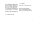
The inputs and outputs are not protected in any way, so care must be taken when connecting anything to these inputs and/or outputs. DIGITAL I/O PIN All inputs and outputs are TTL level compatible. • output current 0.9 mA < Ion < 18 mA, Vce max 40 volt • Pmax 20 mW 2.3.3 Digital I/O The Digital Input and Output connectors give the user the possibility to connect and control a number of devices. For that purpose 6 output and 6 input lines are available.
The common grounds of the inputs 1..5 (see also 2.3.3) are connected to each other. The common ground for the sixth input is separate. The minimal required input current for Ion (the current at which the diode is conducting and emitting light) is 5 mA. When the diode is conducting and thus emitting light, the software will interpret this as a binary ‘1’. The maximum allowed current is 10 mA. When the Inca is reset, the outputs will be in the state Ioff (the transistor is not conducting). 2.3.3.
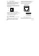
connections for an external power supply, 3-wire serial I/O, the input for an external system reset and a watchdog function. Warning: When using the Micro D to Sub D cable (8122 410 81530) which is also included in the starter kit please notice that the point 7 and 5 are interchanged all other points are interconnected one to one. Micro D; MULTI-PURPOSE I/O PIN 9p-Male 5 4 3 2 1 2.3.4.1 9 8 7 6 1 2 3 4 5 6 7 8 9 FUNCTION Ext. Power RS232 TxD RS232 RxD W-dog alarm-p W-dog alarm-n Ext.
standard cable is available. A user made cable must be connected between the connector pins 9 and 10 where pin 9 is the CVBS connection and pin 10 the ground connection. A 75 ohm coax cable is preferred. Note 1: The RED, GREEN and BLUE signals are 0.7 Vpp signals terminated with 75 ohm load. All other signals are TTL level. Note 2: Some type of video cards use monitor ID #0..#2 to determine the type of monitor used.
2.4 POWERING UP a DHCP server. When this option is enabled all devices on the network will make sure they get a unique IP address by communicating with each other. Fixed IP address The camera is assigned a fixed IP address. This address can be set directly in the camera. Local IP address When all previous options fail, the camera will create an IP address based on the device ID of the camera. In which case the address will always be in the range: 192.168.10.1 to 192.168.10.127.
If during this phase something goes wrong the led will blink in red constantly. During the time that a host can download an application the general purpose LEDs 1 and 2 blink orange alternately. After 3 seconds or a successful application download the Inca will (try to) start the default or downloaded application. If the system LED is blinking during this phase probably the file ‘RapIB320Lcm.rbf’ or the appropriate license file (Rhapsody.key or Clicks.key) don’t reside on the flash file system.
3 SOFTWARE INSTALLATION There is no special software supplied with the Inca for installation purposes, so no installation is necessary. The start-up procedure and running an application is completely done by software control. A number of software products are available supporting the Inca and can be purchased from Industrial Vision. Available are: • The ‘Rhapsody’ package, a powerful set of software tools for writing industrial vision applications.
4 CONFIGURATION The Inca 320 is used in an Ethernet network. This network can be used solely for connecting this camera and other Inca 320 cameras to a PC or it can be part of a much larger existing network with multiple PCs and other Ethernet devices and cameras 4.1 TCP/IP The Inca 320 makes use of TCP/IP, which is a routable protocol.
4.4.2 The format of this file is as follows: [HOST] Domain = yyyy [DEVICES] RAP_DEVICE_1 = RAP_INCA_320 130.144.84.1 RAP_DEVICE_4 = RAP_INCA_320 130.144.84.3 [AUTHORIZATION] RAP_DEVICE_ALL = xxxxxxxx RAP_DEVICE_4 = yyyyyyyy RAP_DEVICE_5 = zzzzzzzz Note that all entries are case sensitive. 4.4.1 Host The host needs to be configured to be in the same domain as the camera, because the host will only detect the cameras that are in the same domain as the host is in.
The password for a given camera can also be globally set in the RapEthernet.ini file. It is a 32 bit number which is specified in 8 hexadecimal digits (leading zeros can be discarded). The default password is 0, which implies using no password at all. The password in the camera and the password specified in the RapEthernet.ini file have to match, otherwise no connection can be established.
5 MECHANICAL INTERFACE For the purpose of installation and handling the camera in an application two mechanical preparations have been made to the camera body: • Three M4 screw holes in the bottom of the camera The one in the camera front end is the most important one because this comprises the sensor.
6 TROUBLE SHOOTING This chapter describes the action to take if the Inca camera does not operate correctly or how to receive support. 6.1 KNOWN PROBLEMS USING THE INCA When using the Micro D to Sub D cable (8122 410 81530) that is also included into the starter kit please notice that the point 5 and 7 are interchanged all other points are interconnected one to one. The cleanness of the sensor is of major importance for the image quality.
6.2 6.2.1 SERVICE AND SUPPORT Service The Inca has built-in identification codes for hard and software in order to facilitate service and support. These codes are displayed during the boot time. If a problem occurs these codes can help to determine quickly the level of equipment being used. The programmable hardware can be altered or updated by downloading a file. There is no need for changing components. 6.2.2 6.2.
7 TECHNICAL SPECIFICATION Power requirements +8..40V, 8 Watt (max) Typically 12..15 Volt Optics C-mount Mechanical Dimensions: 137 x 75 x 50 mm (l x w x h) Outputs Maximum Vce: Digital output: Flash output: Watchdog output: Sensor Size Number of pixels ADC resolution Regions of interest Exposure time 2/3” 1280 x 1024 10 bits 1 programmable Inca 320 Frame rate Electronic shutter Gain programmable Sub-sampling FPN: 27 fields per second Rolling and synchronous 0..10.69 dB factor 2 < 0.
Environmental Inca complies to: EFT immunity: ESD immunity: Emission standard EMC: EDT CE: IEC1000-4-4 IEC1000-4-2 at 4 kV contact discharge and 8 kV through the air EN50082-2 EN50082-1 EN55022 (not mandatory) EN55011 EN61000-4-3 EN61000-4-6 EN61000-4-2 Certified Operating Temperature: Relative humidity: Vibration: 10 oC to 50 oC 20% to 80%, non condensing 0.