INTEGRATED CIRCUITS PDIUSBH12 USB 2-port hub Product specification Supersedes data of 1999 Feb 25 1999 Jul 22
Philips Semiconductors Product specification USB 2-port hub PDIUSBH12 FEATURES DESCRIPTION • Complies with the Universal Serial Bus specification Rev. 1.0 • Complies with the ACPI, OnNOW, and USB power management The Universal Serial Bus Hub PDIUSBH12 is a cost and feature optimized second generation USB Hub with 2 downstream ports and 3 embedded functions (compound hub).
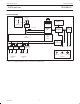
Philips Semiconductors Product specification USB 2-port hub PDIUSBH12 BLOCK DIAGRAM 12 MHz UPSTREAM PORT 3.3V D– D+ 1.
Philips Semiconductors Product specification USB 2-port hub PDIUSBH12 Analog Transceivers Memory Management Unit (MMU) and Integrated RAM These transceivers interface directly to the USB cables through some termination resistors. They are capable of transmitting and receiving serial data at both “full speed” (12 Mbit/s) and “low speed” (1.5 Mbit/s) data rates.
Philips Semiconductors Product specification USB 2-port hub PDIUSBH12 ENDPOINT DESCRIPTIONS There are two endpoint configuration modes supported by the PDIUSBH12, the Single Embedded Function mode and the Multiple (3) Embedded Function mode. The Single Embedded Function mode is the default at power up reset. The Multiple (3) Embedded Function mode can be configured by writing a zero to bit 7 of the first byte of the Set Mode command. Either mode is backward compatible to the PDIUSBH11. Table 1.
Philips Semiconductors Product specification USB 2-port hub PDIUSBH12 PINNING The PDIUSBH12 has two modes of operation. The first mode (Mode 0) configures the pins DNx_GL_N for GoodLink LED indication. The second mode (Mode 1) configures the LED pins as per port overcurrent condition pins. An overcurrent condition on any port can be uniquely identified in Mode 1. However, all downstream ports are disabled as a result of a single overcurrent condition.
Philips Semiconductors Product specification USB 2-port hub PDIUSBH12 Pin description (MODE 0 – Good Link) PIN NO. PIN SYMBOL TYPE DRIVE DESCRIPTION 1 TEST1 Input Connect to Ground for 48MHz crystal input. Connect to VCC for 12MHz crystal input.
Philips Semiconductors Product specification USB 2-port hub PDIUSBH12 Pin description (MODE 1 – Individual Overcurrent) PIN NO PIN SYMBOL TYPE DRIVE DESCRIPTION 1 TEST1 Input Connect to VCC for 48MHz crystal input. Connect to Ground for 12MHz crystal input.
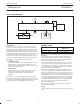
Philips Semiconductors Product specification USB 2-port hub PDIUSBH12 APPLICATION DIAGRAM 3.3V USB UPSTREAM CLKOUT 12MHz I2C µC H12 USB DOWNSTREAM 5V POWER SWITCH AND OVERCURRENT CIRCUIT SWITCHED 5V GOODLINK LED SV00853 I2C Interface ADDRESS TABLE The I2C bus is used to interface to an external microcontroller needed to control the operation of the hub. For cost consideration, the target system microcontroller can be shared and utilized for this purpose.
Philips Semiconductors Product specification USB 2-port hub PDIUSBH12 COMMAND SUMMARY Some commands have the same command code (e.g., Read Buffer and Write Buffer). In these cases, the direction of the Data Phase (read or write) indicates which command is executed.
Philips Semiconductors Product specification USB 2-port hub PDIUSBH12 COMMAND DESCRIPTIONS Set Endpoint Enable Command Procedure Command : D8h There are four basic types of commands: Initialization, Data, Hub Specific, and General commands. Respectively, these are used to initialize the hub and embedded function; for data flow between the hub, embedded function, and the host; some hub specific commands for controlling individual downstream ports; and some general commands.
Philips Semiconductors Product specification USB 2-port hub PDIUSBH12 Connect Downstream Resistors A ‘1’ indicates that downstream resistors are connected. A ‘0’ means that downstream resistors are not connected. The programmed value will not be changed by a bus reset. Configuration Byte 7 1 6 0 5 0 4 0 3 1 2 1 1 0 0 1 POWER ON VALUE REMOTE WAKEUP NO LAZYCLOCK CLOCK RUNNING Non-blinking LEDs A ‘1’ indicates that GoodLink LEDs will NOT blink when there is traffic.
Philips Semiconductors Product specification USB 2-port hub PDIUSBH12 Data Flow Commands Select Endpoint Data flow commands are used to manage the data transmission between the USB endpoints and the monitor. Much of the data flow is initiated via an interrupt to the microcontroller. The microcontroller utilizes these commands to access and determine whether the endpoint FIFOs have valid data.
Philips Semiconductors Product specification USB 2-port hub PDIUSBH12 Table 3.
Philips Semiconductors Product specification USB 2-port hub PDIUSBH12 Set Endpoint Status Hub Commands Command : 40–4Dh Data : Write 1 byte Hub commands are used to report connectivity and power status between the hub and the host. These commands allow the host to enable each port individually and get any change of status such as new connectivity information. A stalled control endpoint is automatically unstalled when it receives a SETUP token, regardless of the content of the packet.
Philips Semiconductors Product specification USB 2-port hub PDIUSBH12 Port Status Change Byte The description for the Port Status Change Byte is similar to the Port Status Byte except that the value of the bits are ‘1’ only when a change has occurred. Get Port Status Command : E0h–E1h Data : Read 1 or 2 bytes 7 X The Get Port Status Command can be followed by one or two data reads. The first byte returned contains the port status. The second byte returned is the port status change byte.
Philips Semiconductors Product specification USB 2-port hub PDIUSBH12 General Commands Host Requests SetFeature PORT_RESET Send Resume Command : F6h Data : None Reinitialize the embedded function and set the Reset Change bit to indicate that the reset has completed. Reset the Enable Status bit, enable the embedded function and set its address to ‘0’ by the Set embedded function Address / Enable command. Disable the embedded function interrupt endpoint by the Set Endpoint Enable command.
Philips Semiconductors Product specification USB 2-port hub PDIUSBH12 RECOMMENDED OPERATING CONDITIONS SYMBOL VCC PARAMETER TEST CONDITIONS MIN MAX UNIT 3.0 3.6 V DC input voltage range 0 5.5 V VI/O DC input voltage range for I/O 0 5.
Philips Semiconductors Product specification USB 2-port hub PDIUSBH12 DC CHARACTERISTICS (Digital pins) SYMBOL PARAMETER TEST CONDITIONS MIN TYP MAX UNIT 0.6 V Input Levels VIL LOW level input voltage VIH HIGH level input voltage 2.7 V VTLH LOW to HIGH threshold voltage ST (Schmitt Trigger) pins 1.4 1.9 V VTHL HIGH to LOW threshold voltage ST pins 0.9 1.5 V VHYS Hysteresis voltage ST pins 0.4 0.7 V 0.4 0.
Philips Semiconductors Product specification USB 2-port hub PDIUSBH12 AC CHARACTERISTICS (AI/O pins, FULL speed) SYMBOL PARAMETER Driver characteristics tr tf Transition Time: Rise time Fall time tRFM Rise/fall time matching VCRS Output signal crossover voltage TEST CONDITIONS MIN MAX UNIT 4 4 20 20 ns ns CL = 50pF; Rpu = 1.5kΩ on D+ to VCC Between 10% and 90% (tr/tf) 90 110 % 1.3 2.
Philips Semiconductors Product specification USB 2-port hub PDIUSBH12 AC CHARACTERISTICS (AI/O pins, LOW speed) SYMBOL PARAMETER Transition Time tlff tRFM VLCRS MIN MAX UNIT CL = 50pF and 350pF; Rpu = 1.5kΩ on D– to VCC Driver characteristics tlr TEST CONDITIONS Between 10% and 90% CL = 50pF Rise time 75 CL = 350pF CL = 50pF Fall time 75 CL = 350pF Rise/fall time matching ns 300 (tr/tf) Output signal crossover voltage ns ns 300 ns 80 120 % 1.3 2.
Philips Semiconductors Product specification USB 2-port hub PDIUSBH12 VDD CROSSOVER POINT CROSSOVER POINT DOWNSTREAM DIFFERENTIAL DATA UPSTREAMDIFFERENTIAL DATA VSS CROSSOVER POINT Hub Delay Downstream tHDD DOWNSTREAMDIFFERENTIAL DATA CROSSOVER POINT Hub Delay Upstream tHDD UPSTREAM DIFFERENTIAL DATA VSS A. DOWNSTREAM HUB DELAY B. UPSTREAM HUB DELAY SOP DISTORTION tSOP = tHDD(SOP) – tHDD (NEXT J) LOW SPEED TIMINGS ARE DETERMINED IN THE SAME WAY FOR: tLHDD AND tLSOP SV00514 Figure 2.
Philips Semiconductors Product specification USB 2-port hub PDIUSBH12 AC CHARACTERISTICS (I2C pins) All timing values are valid within the operating supply voltage and ambient temperature range and reference to VIL and VIH with an input voltage swing of VSS and VDD. PARAMETER SYMBOL TEST CONDITIONS MIN MAX UNIT 1000 kHz fSCL SCL clock frequency tBUF Bus free time 0.5 µs tSU;STA Start condition set-up time 0.25 µs tHD;STA Start condition hold time 0.25 µs tLOW SCL LOW time 0.
Philips Semiconductors Product specification USB 2-port hub PDIUSBH12 SO28: plastic small outline package; 28 leads; body width 7.
Philips Semiconductors Product specification USB 2-port hub PDIUSBH12 DIP28: plastic dual in-line package; 28 leads (600 mil) 1999 Jul 22 25 SOT117-1
Philips Semiconductors Product specification USB 2-port hub PDIUSBH12 SOLDERING Introduction This text gives a very brief insight to a complex technology. A more in-depth account of soldering ICs can be found in our “Data Handbook IC26; Integrated Circuit Packages” (document order number 9398 652 90011).
Philips Semiconductors Product specification USB 2-port hub PDIUSBH12 SUITABILITY OF IC PACKAGES FOR WAVE, REFLOW AND DIPPING SOLDERING METHODS Soldering Method Mo nting Mounting Through-hole mount Package DBS, DIP, HDIP, SDIP, SIL BGA, SQFP, HLQFP, HSQFP, HSOP, SMS Surface mount PLCC, SO, SOJ LQFP, QFP, TQFP SSOP, TSSOP, VSO Reflow 1 Dipping suitable 2 – suitable not suitable suitable – suitable – Wave not suitable 3 suitable suitable – not recommended 4, 5 suitable – not recomme
Philips Semiconductors Product specification USB 2-port hub PDIUSBH12 Data sheet status Data sheet status Product status Definition [1] Objective specification Development This data sheet contains the design target or goal specifications for product development. Specification may change in any manner without notice. Preliminary specification Qualification This data sheet contains preliminary data, and supplementary data will be published at a later date.