DISCRETE SEMICONDUCTORS General Magnetoresistive sensors for magnetic field measurement 2000 Sep 06
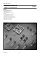
Philips Semiconductors Magnetoresistive sensors for magnetic field measurement General CONTENTS General field measurement • Operating principles • Philips magnetoresistive sensors • Flipping • Effect of temperature on behaviour • Using magnetoresistive sensors • Further information for advanced users • Appendix 1: The magnetoresistive effect • Appendix 2: Sensor flipping • Appendix 3: Sensor layout. Fig.1 Philips magnetoresistive sensors.
Philips Semiconductors Magnetoresistive sensors for magnetic field measurement General The KMZ range of magnetoresistive sensors is characterized by high sensitivity in the detection of magnetic fields, a wide operating temperature range, a low and stable offset and low sensitivity to mechanical stress.
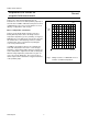
Philips Semiconductors Magnetoresistive sensors for magnetic field measurement handbook, halfpage General In this basic form, the MR effect can be used effectively for angular measurement and some rotational speed measurements, which do not require linearization of the sensor characteristic. R In the KMZ series of sensors, four permalloy strips are arranged in a meander fashion on the silicon (Fig.4 shows one example, of the pattern on a KMZ10).
Philips Semiconductors Magnetoresistive sensors for magnetic field measurement General Two further resistors, RT, are included, as shown in Fig.5. These are for trimming sensor offset down to (almost) zero during the production process. For some applications however, the MR effect can be used to its best advantage when the sensor output characteristic has been linearized.
Philips Semiconductors Magnetoresistive sensors for magnetic field measurement General Flipping The field (e.g. ‘−Hx’) needed to flip the sensor magnetization, and hence the characteristic, depends on the magnitude of the transverse field ‘Hy’: the greater the field ‘Hy’, the smaller the field ‘−Hx’.
Philips Semiconductors Magnetoresistive sensors for magnetic field measurement General Figure 7 also shows that the flipping itself is not instantaneous, because not all the permalloy strips flip at the same rate. In addition, it illustrates the hysteresis effect exhibited by the sensor. For more information on sensor flipping, see Appendix 2 of this chapter.
Philips Semiconductors Magnetoresistive sensors for magnetic field measurement General MLC134 handbook, full pagewidth 15 VO (mV/V) o Tamb = 25 C 25 oC 10 75 oC 5 125o C 0 5 10 operating range 15 3 Fig.9 2 1 0 1 2 3 H y (kA/m) Output voltage ‘Vo’ as a fraction of the supply voltage of a KMZ10B sensor as a function of transverse field ‘Hy’ for several temperatures.
Philips Semiconductors Magnetoresistive sensors for magnetic field measurement General Figure 10 is similar to Fig.9, but with the sensor powered by a constant current supply. Figure 10 shows that, in this case, the temperature dependency of sensitivity is significantly reduced. This is a direct result of the increase in bridge resistance with temperature (see Fig.8), which partly compensates the fall in sensitivity by increasing the voltage across the bridge and hence the output voltage.
Philips Semiconductors Magnetoresistive sensors for magnetic field measurement General linear characteristics is required for compensation. Philips KTY series are well suited for this purpose, as their positive Temperature Coefficient (TC) matches well with the negative TC of the MR sensor.
Philips Semiconductors Magnetoresistive sensors for magnetic field measurement General Further information for advanced users THE MR EFFECT In sensors employing the MR effect, the resistance of the sensor under the influence of a magnetic field changes as it is moved through an angle α as given by: 2 R = R O + ∆R O cos α (2) I It can be shown that 2 H 2 sin α = ------- for H ≤ H O 2 HO ,,, ,, ,,,, ,,, ,,, ,,,,,, ,,, ,,, ,,, ,,,,,, ,,, ,,, ,,, Barber pole handbook, halfpage (3) I MLC125 Permallo
Philips Semiconductors Magnetoresistive sensors for magnetic field measurement General 2 ∆R O H H R = R O + ----------- + ∆R O -------- 1 – ------2 HO 2 H (7) O The equation is linear where H/Ho = 0, as shown in Fig.7. Likewise, for sensors using Barber poles arranged at an angle of −45°, the equation derives to: R handbook, halfpage 2 ∆R O H H R = R O + ----------- – ∆R O -------- 1 – ------2HO 2 H (8) 0 This is the mirror image of the characteristic in Fig.7.
Philips Semiconductors Magnetoresistive sensors for magnetic field measurement General The greater the auxiliary field, the greater the disturbing field that can be tolerated before flipping occurs. For auxiliary fields above 3 kA/m, the SOAR graph shows that the sensor is completely stable, regardless of the magnitude of the disturbing field. It can also be seen from this graph that the SOAR can be extended for low values of ‘Hy’. In Fig.
Philips Semiconductors Magnetoresistive sensors for magnetic field measurement General VS handbook, full pagewidth OP1 R10 RT R12 KTY82-110 R14 R5 R1 RA VO OP3 R6 R4 R13 offset RB R3 R7 R9 OP2 R11 KMZ10B R2 MLC145 Fig.16 KMZ10B application circuit with instrumentation amplifier.
Philips Semiconductors Magnetoresistive sensors for magnetic field measurement General Figure 17 shows the geometry of a simple sensor where the thickness (t) is much smaller than the width (w) which is in turn, less than the length (l) (i.e. t « w ‹ l). With the current (I) flowing in the x-direction (i.e.
Philips Semiconductors Magnetoresistive sensors for magnetic field measurement General resistance-field (R-H) dependence, so a simple magnetoresistive element cannot be used directly for linear field measurements. A magnetic biasing field can be used to solve this problem, but a better solution is linearization using barber-poles (described later).
Philips Semiconductors Magnetoresistive sensors for magnetic field measurement General BARBER-POLE SENSORS equal widths. The characteristic is plotted in Fig 20 and it can be seen that for small values of Hy relative to H0, the R-H dependence is linear. In fact this equation gives the same linear R-H dependence as the planar Hall-effect sensor, but it has the magnitude of the magnetoresistive sensor.
Philips Semiconductors Magnetoresistive sensors for magnetic field measurement General requires a high sensor resistance R with a large area A, since there are limits for power dissipation and current density. The current density in permalloy may be very high (j > 106 A/cm2 in passivation layers), but there are weak points at the current reversal in the meander (see section on sensor layout) and in the barber-pole material, with five-fold increased current density.
Philips Semiconductors Magnetoresistive sensors for magnetic field measurement General the more the magnetization rotates towards 90˚ and therefore it becomes easier to flip the sensor into the corresponding stable position in the ‘-x’ direction. This means that a smaller -Hx field is sufficient to cause the flipping action this also considerably enlarges Hk. If a small temperature coefficient of ∆ρ is required, NiCo alloys are preferable.
Philips Semiconductors Magnetoresistive sensors for magnetic field measurement handbook, full pagewidth General MLC132 150 VO (mV) Hx = 4 kA/m 100 2 kA/m 1 kA/m 50 0 0 2 4 6 8 10 12 H y (kA/m) Fig.23 Sensor output ‘Vo’ as a function of the transverse field Hy. A Safe Operating ARea (SOAR) can be determined for magnetoresistive sensors, within which the sensor will not flip, depending on a number of factors.
Philips Semiconductors Magnetoresistive sensors for magnetic field measurement General APPENDIX 3: SENSOR LAYOUT different for these three families of sensors in every case, the elements are linked in the same fashion to form the four arms of a Wheatstone bridge. The meander pattern used in the KMZ51 is more sophisticated and also includes integrated compensation and flipping coils (see chapter on weak fields); the KMZ41 is described in more detail in the chapter on angle measurement.
Philips Semiconductors Magnetoresistive sensors for magnetic field measurement General In one pair of diagonally opposed elements the barber-poles are at +45˚ to the strip axis, with the second pair at −45˚. A resistance increase in one pair of elements due to an external magnetic field is matched by an equal decrease in resistance of the second pair.
Philips Semiconductors Magnetoresistive sensors for magnetic field measurement General static offset, an offset drift due to temperature variations of about 6 (µV/V)K−1 can be expected and assuming an ambient temperature up to 100 °C, the resulting offset can be of the order of 2 mV/V.
Philips Semiconductors Magnetoresistive sensors for magnetic field measurement ,,,, ,,, , ,, ,,,, ,,,, Flipping causes a change in the polarity of the sensor output signal and this can be used to separate the offset signal from the measured signal. Essentially, the unknown field in the ‘normal’ positive direction (plus the offset) is measured in one half of the cycle, while the unknown field in the ‘inverted’ negative direction (plus the offset) is measured in the second half.
Philips Semiconductors Magnetoresistive sensors for magnetic field measurement handbook, full pagewidth General T T T flipping current IF time internal magnetization VO VO offset Hy time (a) VO time (b) VO time (c) MBH618 Fig.30 Timing diagram for flipping circuit (a) output voltage; (b) filtered output voltage; (c) output voltage filtered and demodulated.
Philips Semiconductors Magnetoresistive sensors for magnetic field measurement General not negligible, as it can produce a difference of a factor of three within a −25 °C to +125 °C temperature range, for fields up to 0.5 kA/m. This effect is not compensated for by the flipping action described in the last section. SENSOR TEMPERATURE DRIFT The sensitivity of MR sensors is also temperature dependent, with sensitivity decreasing as temperature increases (Fig.31).
Philips Semiconductors Magnetoresistive sensors for magnetic field measurement General The simplest form of temperature compensation is to use a current source to supply to the sensor instead of a voltage source. In this case, the resulting reduction in sensitivity due to temperature is partially compensated by a corresponding increase in bridge resistance.
Philips Semiconductors Magnetoresistive sensors for magnetic field measurement General The optimal method of compensating for temperature dependent sensitivity differences in MR measurements of weak fields uses electro-magnetic feedback. As can be seen from the sensor characteristics in Figs 31 and 32, sensor output is completely independent of temperature changes at the point where no external field is applied (the null-point).
Philips Semiconductors Magnetoresistive sensors for magnetic field measurement General The influence of other disturbing fields can also be eliminated provided they are well known, by adding a second current source to the compensating coil. Such fields might be those arising from the set-up housing, ferromagnetic components placed close to the sensor or magnetic fields from electrical motors.