Digital Business System Section 530 ISDN Reference Manual for CPC-EX Version 2.3 Doc. No.
The contents of this document are subject to change without notice and do not constitute a commitment on the part of Panasonic Telecommunication Systems Company (PTSC). Every effort has been made to ensure the accuracy of this document. However, due to ongoing product improvements and revisions, Panasonic cannot guarantee the accuracy of printed material after the date of publication nor can it accept responsibility for errors or omissions. Panasonic will update and revise this document as needed.
Contents About This Manual Overview............................................................................................................................ vii Related Documents ............................................................................................................ vii Chapter 1. Introduction to the ISDN Interface Overview.................................................................................................................................
Chapter 4. Programming Reference ISDN System Settings ............................................................................................................ 4-3 System Size....................................................................................................................... 4-3 T1/ISDN............................................................................................................................ 4-3 Clock Settings ...........................................................
List of Figures Figure 2-1 Figure 2-2 Figure 2-3 Figure 2-4 Figure 2-5 Figure 2-6 Figure 2-7 Figure 2-8 Figure 2-9 Figure 2-10 Figure 4-1 Figure 4-2 Figure 4-3 CSU installation .......................................................................................... 2-13 SCC-B Switch 4 .......................................................................................... 2-15 Connector 4 (CN4) strapping, Sync Unit .................................................... 2-15 Sync Unit installation .......
List of Tables Table 1-1 Table 4-1 Table 5-1 Table 5-2 Table 5-3 Table 6-1 Table 6-2 Table 6-3 Table 6-4 Table 6-5 Table 6-6 Table 6-7 Table 6-8 Table 6-9 Table 6-10 Table 6-11 Table 7-1 Table 7-2 vi Guidelines for ordering ISDN services ......................................................... 1-4 ISDN alarm definitions ............................................................................... 4-17 ISDN Hardware requirements for single-cabinet systems ............................
About This Manual Overview This manual provides an overview of the DBS ISDN Interface, along with installation and programming instructions when used with CPC-EX Version 2.2. Appendix A provides updates for CPC-EX version 2.3 as well. The following table summarizes each chapter contained in this manual. Chapter Title Introduction to the 1 ISDN Interface Installation 2 Purpose Provides an overview of the DBS ISDN Interface, plus information on pre-installation requirements.
viii DBS-EX23-530 Revised April 2000
Chapter 1. Introduction to the ISDN Interface This chapter provides an overview of the ISDN Interface. It also describes pre-installation requirements for the ISDN. The following table summarizes the topics contained in this chapter.
1-2 DBS-EX23-530 Revised April 2000
Introduction to the ISDN Interface Overview Overview Description of the ISDN Interface The ISDN Interface is a Primary Rate Interface (PRI) digital trunk card that provides 23 voice channels (“B” channels) and a control channel (“D” channel) over a four-wire circuit. ISDN lines can be leased from local exchange carriers and long-distance carriers. Note: The current version of the ISDN supports voice communications only. Data can be transmitted only if it reaches the ISDN in analog form.
Pre-Installation Requirements Introduction to the ISDN Interface Pre-Installation Requirements Use the following guidelines to prepare your site for ISDN installation. Ordering ISDN The ISDN PRI provides a flexible method of providing access to the PSTN (Public Switched Telephone Network). Because of the numerous ways that an ISDN span can be configured by the CO, it is essential that the DBS configuration and the provisioning of the CO be compatible.
Introduction to the ISDN Interface Pre-Installation Requirements 9 Long distance Carrier (IntraLATA) (LPIC) This identifies the carrier who will provide access for connections, which are not local but are still within the local LATA. 10 Request date of installation 11 Facility type ISDN PRI 12 Facility quantity 1 or 2 spans NOTE THAT THE FOLLOWING ITEMS MUST BE PROVIDED ON A PER SPAN BASIS 13 Signaling code DS-1 (1.
Pre-Installation Requirements Introduction to the ISDN Interface Copy the following tables for each site and span that is to be installed. Complete all information and use for future reference. Note that certain parameters are shown with default values. # Information Needed from CO 1 Manufacture of CO and software load 2 Is local dialing 7 digits, 10 digits or a combination. 3 For long distance dialing does the CO want to see a leading “1” or not.
Introduction to the ISDN Interface Pre-Installation Requirements Span Item Master Cabinet Span 13 Signaling code DS-1 DS-1 14 Line coding B8ZS B8ZS 15 Framing Format ESF ESF 16 Bearer configuration Voice or Voice/Data Voice or Voice/Data 17 Quantity of B (bearer) channels 18 Call type Two-way Two-way 19 Quantity of phone numbers 20 Number of incoming digits to CPE (Customer Premise Equipment –DBS) 4 digits 4 digits 21 ISDN PRI Protocol 22 Glare Resolution CPE yield to CO
Pre-Installation Requirements Introduction to the ISDN Interface What You Must Purchase The following items must be purchased to install ISDN. DBS Equipment If you are installing the ISDN in a single-cabinet system, order the equipment included in Table 1-1. For two-cabinet systems, see Table 1-2. Table 1-1. ISDN Hardware requirements for single-cabinet systems CPC-EX (VB-43415) SCC-B (VB-43421) 1 ISDN Trunk Card (VB-43571) 1 (See Note 1.) MDF Card (VB-43562) 1 (See Note 3.
Introduction to the ISDN Interface Pre-Installation Requirements CSU Equipment The installer must provide a Channel Service Unit (CSU) plus CSU cabling. The CSU equipment must meet the specifications contained in Table 1-3. See page 2-12 for instructions on installing the CSU. Table 1-3. CSU equipment required for ISDN Item CSU CSU Cabling Specifications Vendors The Channel Service Unit (CSU) must comply with FCC Part 15 and Part 68. The CSU is installed between the DBS and the public network.
Pre-Installation Requirements 1-10 Introduction to the ISDN Interface DBS-EX23-530 April 2000
Chapter 2. Installation This section describes guidelines and procedures for installing the ISDN Interface. Once the ISDN Interface is installed, refer to Chapter 3 - “Quick Start Programming” or Chapter 4 - “Programming Reference” for programming instructions. This chapter covers the following topics.
2-2 DBS-EX22-530 Revised April 2000
Installation Guidelines Guidelines Read the following guidelines before beginning ISDN installation. Installation instructions begin on page 2-14. Hardware Requirements • The system configuration determines what cards and cables must be purchased for ISDN. See “DBS Equipment” on page 1-8 for more information. • The installer must provide a Channel Service Unit (CSU) that complies with FCC Part 15 and Part 68. The CSU is installed between the DBS and the public network.
Guidelines Installation • Fractional ISDN can be used when fewer than 23 ISDN trunks are needed. Fractional ISDN allows you to use only a portion of the 23 channels provided on the ISDN card. • Fractional ISDN per port assignments require the VB-43511A version of the loop start trunk card. The older VB-43511 version may be used with fractional ISDN but requires that the trunks be assigned in blocks of 8.
Installation Guidelines Trunk Assignments for Single-Cabinet Systems • Programming is not required to associate trunk ports with slot locations. However, you must use programming to specify that a combination of ISDN and analog trunks is installed, and you must also specify how many ISDN channels are used. • Fractional ISDN per port assignments require the VB-43511A version of the loop start trunk card.
Guidelines Installation Table 2-4.
Installation Guidelines Table 2-5.
Guidelines Installation Table 2-7.
Installation Guidelines Table 2-8.
Guidelines Installation Table 2-9.
Installation Guidelines Table 2-10.
Installation Procedures Installation Installation Procedures The following procedures provide step-by-step instructions for installing the CSU and the ISDN Interface. The ISDN procedure that you should use depends on the type of system you have and the number of ISDNs you are installing. If you’re installing ...
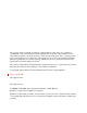
Installation Installation Procedures Figure 2-1. CSU installation 2. Connect the network cable from the network side of the CSU to the network demarcation point. (The network demarcation is typically an RJ48C “smartjack.”) 3. Test the CSU cabling by performing the following steps. Note: The following procedure can only be used with CSUs that provide a local loopback. When testing the CSU, be sure it is set to “local loopback,” rather than “line loopback.
Installation Procedures Installation Sync Source Trunk Configuration ISDN Trunk Type 4-4 to 4-6 4-16 4-28 a. Remove the jumper from CN4 on the Sync Card (Figure 2-3 on page 215). b. Put the CSU in the local loopback mode. c. Check the CFA LED on the ISDN card. If the LED is dark, the cabling between the CSU and DBS is okay. If the LED is lit, go to the next step. d. Check the cabling from the DBS to the CSU. e.
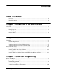
Installation Installation Procedures Figure 2-2. SCC-B Switch 4 M ode B M ode A (C PC -B C PC -EX) (C PC -A C PC -AII) SW 4 SC C -B C ard 3. Check connector 4 (CN4) on the Sync Unit (VB-43563). Make sure that Pins 2 and 3 are strapped. (See Figure 2-3.) When Pins 2 and 3 are strapped, the Sync Unit synchronizes the DBS ISDN card with the signaling provided by the public network. Figure 2-3. Connector 4 (CN4) strapping, Sync Unit CN2 CN3 CN4 CN1 1 3 Free N et 4.
Installation Procedures Installation Note: Before attaching the Sync Unit, insert the three spacers provided with the unit and remove the jumpers from CN2 of the CPC-EX card. Figure 2-4.
Installation Installation Procedures 5. Install the MDF (main distribution frame) card in the top of the cabinet as shown in Figure 2-5. Figure 2-5.
Installation Procedures Installation 6. Set SW1 on the ISDN card according to the following table. These switch settings correspond to the distance between the DBS and the CSU. To turn a switch on, flip it to the “up” position. Table 2-11. Switch settings for SW1 on the ISDN card SW SW1 SW2 SW3 SW4 SW5 SW6 SW7 SW8 0 to 150 ft. On Off Off Off Off Off Off Not used Distance from the DBS to the CSU 150-450 ft. 450-655 ft. Off Off On Off Off On On Off Off On On Off Off On Not used Not used 7.
Installation Installation Procedures 9. Connect the cable attached to CN3 on the MDF card to CN3 on the ISDN card (Figure 2-8). 10. Using an RJ48 cable, connect CN1 on the MDF card to the CSU (Figure 2-8). The following illustration shows CN1 pinouts. Figure 2-7.
Installation Procedures Installation 11. Connect the ground cable from the MDF card to the cabinet as shown in Figure 2-8. Figure 2-8.
Installation Installation Procedures Installing ISDN in a Double Cabinet with the ISDN in the Slave 1. Before beginning ISDN installation, perform the “ISDN Function Reset” command (FF1 9# 1# 1#). This command must be issued before the ISDN can be installed properly. 2. Check SW4 on the SCC-B card. Be sure it is set to “Mode B.” (See Step 2 on page 2-14.) 3. Install the Sync Unit in the master cabinet as described in Steps 3 and 4 on pages 2-15 and 2-15. 4. Install an MDF card in the slave cabinet.
Installation Procedures Installation Figure 2-9.
Installation Installation Procedures Installing ISDN in a Double Cabinet with ISDNs in the Master and Slave 1. Before beginning ISDN installation, perform the “ISDN Function Reset” command (FF1 9# 1# 1#). This command must be issued before the ISDN can be installed properly. 2. Check SW4 on the SCC-B card. Be sure it is set to “Mode B.” (See Step 2 on page 2-14.) 3. Install the Sync Unit in the master cabinet as described in Steps 3 and 4 on pages 2-15 and 2-15. 4. Install an MDF card in each cabinet.
Figure 2-10. Clock sync cable and sync cable connections, double-cabinet installation MDF Slot Label Connector Slave Cabinet TRK1 TRK2 TRK3 EC1 EC2 EC3 EC4 EC5 EC6 EC7 EC8 EC/TRK SCC CPC AUX1 AUX2 Guide CN3 SW1 CN4 Card Label DEC TRK DEC DEC DEC DEC DEC DEC DEC I S D N TRK N O T MFR 1 MFR 2 CBL (S) CN5 U S E D MDF Slot Label Connector Master Cabinet Interconnection Cables TRK1 TRK2 T RK3 EC1 EC2 EC3 EC4 EC5 EC6 EC7 EC8 EC/TRK SCC CPC AUX1 AUX2 Guide Clock Sync.
Chapter 3. Quick-Start Programming The ISDN Interface includes many programming options, which allow you to customize how your ISDN is used. In most cases, however, you only need to set a few of the programs to get your ISDN online. This chapter summarizes the programs that are essential to ISDN installation. The following table shows the topics that are described in this chapter. For detailed descriptions of all the ISDN programs, see Chapter 4 “Programming Reference.
3-2 DBS-EX23-530 Revised April 2000
Quick-Start Programming Before You Begin Before You Begin Before you begin programming, you should be familiar with resetting the DBS and performing the “ISDN Data Reset” command. The following paragraphs explain when these two procedures are used. The ISDN Data Reset command. If you are installing ISDN while you are upgrading to a new DBS release, perform the “ISDN Data Reset” before you begin ISDN programming. Manually Resetting the DBS. Many of the ISDN programs require a manual reset to take effect.
Programming Initial ISDN Options Quick-Start Programming Programming Initial ISDN Options The following instructions explain the minimum programming required to make the ISDN operational, plus the programming required for DID. Each instruction includes a page number that references the relevant detailed descriptions in Chapter 4. Default settings appear in bold. Minimum Programming Note:Option settings are in parenthesis ( ). 1. Set the system for ISDN operation.
Quick-Start Programming Programming Initial ISDN Options 4. Assign the sync sources (pages 4-4 to 4-6).
Programming Initial ISDN Options Quick-Start Programming 7. Specify which trunk channels are used for ISDN (page 4-28). Address FF2 (1-64)# 21# (5)# Options 0= Loop start 1=Ground start 2=DID 3=T1 4=CID 5=ISDN Master Cabinet Setup Note:Refer to “Typical Central Office Configurations” on page 3-10 for setting below options. Default setting are in BOLD. 8.
Quick-Start Programming Programming Initial ISDN Options Address FF1 9# 4# 4# 5# 5# (0-1)# ISDN International Dial Code Deduction Options 0-Send as is 1-Deduct 011 from the code Address FF1 9# 4# 4# 5# 6# (0-1)# ISDN Long Distance Code“1”Deduction Options 0-Send as is 1-Deduct “1” from the code Address FF1 9# 4# 4# 5# 7# (0-1)# ISDN Type and Plan Option Options 0-Determine Type and Plan 1-Always Type and Plan set to Unknown/Unknown Slave Cabinet Set-Up Note:Refer to “Typical Central Office Con
Quick-Start Programming Address Options Programming Initial ISDN Options FF1 9# 4# 5# 5# 3# (0-2)# NSF 0-None 1-SDN 2-MegaCom Address FF1 9# 4# 5# 5# 4# (0-3)# ISDN CO Type Options 0-4ESS 1-5ESS 2- Reserved 3- DMS100 Address FF1 9# 4# 5# 5# 5# (0-1)# ISDN International Dial Code Deduction Options 0-Send as is 1-Deduct 011 from the code Address FF1 9# 4# 5# 5# 6# (0-1)# ISDN Long Distance Code“1”Deduction Options 0-Send as is 1-Deduct “1” from the code Address FF1 9# 4# 5# 5# 7# (0-1)# ISDN
Quick-Start Programming Programming Initial ISDN Options 12. Specify the extension number to call for each ISDN incoming DID number (page 4-29). Address FF1 9# 3# (0000-9999)# (100-699)# 13. Some ISDN lines provide Automatic Number Identification (ANI). This service is similar to Caller ID by providing the number of the calling party. For DID calls with ANI information provided, determine if ANI data or DID data is displayed on the called telephone..
Quick-Start Programming Programming Initial ISDN Options Typical Central Office Configurations Note:Unless stated all other default values are correct. Lucent (AT&T) 4ESS CO Type (0) 4ESS NSF- None(0) or MegaCom(2) – Depends on service requested from CO. ISDN international code deduct “011” - Set to (1) Deduct “011” from being sent in Setup message to CO. ISDN Long Distance “1”Code Deduction - Set to (1) Deduct “1” from being sent in Setup message to CO.
Chapter 4. Programming Reference This chapter describes programming parameters for the ISDN Interface. The descriptions of each parameter include a list of available options and the associated programming address. Default options appear in bold. This chapter is intended for readers who are familiar with DBS programming. For an introduction to DBS programming, see the Programming Guidance Manual, Section 400. The following table lists the topics described in this chapter.
4-2 DBS-EX23-530 Revised April 2000
Programming Reference ISDN System Settings ISDN System Settings System Size Parameter System Configuration Description Identifies the system size. Note: For changes to this parameter to take effect, the system must be powered down, then back up again. Programming FF1 9# 4# 1# 1# (0-8)# Options 0=DBS 40 1=DBS 72 2=DBS 96 3=DBS 40 + DBS 40 (ISDN must be in the slave cabinet.) 4=DBS 72 + DBS 40 (ISDN is not supported.) 5=DBS 72 + DBS 72 (ISDN must be in the slave cabinet.
ISDN System Settings Programming Reference Clock Settings Parameter Sync Source 1 Description The Sync Card (installed on the CPC-EX) provides a method of synchronizing the DBS with the public network. This parameter determines the first clocking source for network synchronization. If the first source fails, the system will switch to the second source. The system will attempt to go back to the first source based on the value entered under “Network Re-sync Timer” (page 4-7).
Programming Reference ISDN System Settings Parameter Sync Source 2 Description Determines the source of clocking for the second sync source. The second sync source is used if the first sync source fails. The system will attempt to switch from the second source back to the first source based on the value entered under “Network Re-sync Timer” (page 4-7). If the second source fails and the first source is not working, the system will switch to the third source.
ISDN System Settings Programming Reference Parameter Sync Source 3 Description Determines the source of clocking for the third sync source. The third sync source is used if both the first and second source fail. The system will attempt to switch from the third source back to the first source based on the value entered under “Network Re-sync Timer” (page 4-7). In most cases, a system with one ISDN has the 3rd sync source set to “0.” Systems with two ISDNs normally have the 3rd sync source set to “3.
Programming Reference System-Wide Timers System-Wide Timers Parameter Network Re-sync Timer Description If one clock source fails, the system will switch to another clock source. The re-sync timer determines how often the system attempts to return to the original clock source. For example, if the first clock source (1st sync) fails, the system switches to the second source. However, the system will try to return to the first source based on the re-sync timer.
System-Wide Timers Programming Reference Parameter Ringing Timer (T301) Description Determines how long the called party will ring before the DBS will disconnect the call. Programming FF1 9# 4# 2# 2# (0-15)# Options 0-10 0=180 sec. 1=20 sec. 2=40 sec. 3=60 sec. . . . 11=220 sec. 12=240 sec. 13=240 sec. 14=240 sec. 15=Infinite Parameter Call Setup Timer (T303) Description Determines the time limit for a CO to respond to an outgoing call attempt.
Programming Reference System-Wide Timers Parameter Disconnect Request Timer (AT&T) (T305) Description Determines the time allocated for the CO to disconnect a call before the DBS disconnects the call. Programming FF1 9# 4# 2# 4# (0-10)# Options 0-10 0=4 sec. 1=1 sec. 2=2 sec. 3=3 sec. 4=4 sec. 5=5 sec. 6=6 sec. 7=7 sec. 8=8 sec. 9=9 sec. 10=10 sec.
System-Wide Timers Programming Reference Parameter Release Request Timer (T308) Description Determines the time allocated for the CO to acknowledge a disconnect/release. Programming FF1 9# 4# 2# 6# (0-10)# Options 0-10 0=4 sec. 1=1 sec. 2=2 sec. 3=3 sec. 4=4 sec. 5=5 sec. 6=6 sec. 7=7 sec. 8=8 sec. 9=9 sec. 10=10 sec. Parameter Outbound Call Processing Timer (T310) Description Determines the time allocated for the CO to deliver a call. If the call is not delivered, the DBS will clear the call.
Programming Reference System-Wide Timers Parameter Connect Request Timer (T313) Description Determines the time the DBS waits for the CO to acknowledge that a call has been connected. Programming FF1 9# 4# 2# 8# (0-15)# Options 0-10 0=4 sec. 1=1 sec. 2=2 sec. 3=3 sec. 4=4 sec. 5=5 sec. 6=6 sec. 7=7 sec. 8=8 sec. 9=9 sec. 10=10 sec.
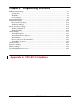
Digital Pad Settings Programming Reference Digital Pad Settings Parameter Description Digital Pad Settings Adjusts the volume of connections made via the ISDN. Default volume levels are included for connections between different types of terminals or circuits. For example, a K-TEL to ISDN connection may use one volume setting, while an SLT-to-ISDN connection may use another. The volume settings are controlled by changing a pad number, which in turn changes the loss or gain of the connection.
Programming Reference Options Digital Pad Settings Figure 4-2 shows the default values for the most common ISDN connections. Figure 4-3 lists the adjustments provided by each pad number. Figure 4-2. Default pad values Figure 4-3. Pad Nos. From To Setting Value Pad No. ISDN #1 K-TEL 16 -2 dB 0 0 dB ISDN #2 K-TEL 16 -2 dB 1 +2 dB ISDN #1 SLT 16 -2 dB . . ISDN #2 SLT 16 -2 dB . . K-TEL ISDN #1 16 -2 dB . .
Digital Pad Settings Programming Reference Extension Port Settings Parameter Station Port Class Description By default, DBS phones are assigned a circuit type, based on whether they are KTELs or SLTs. The circuit type is used with digital pad settings to determine the loss/gain settings for connections to the ISDN. (See “Digital Pad Setting” on page 4-12.) The Port Class parameter is provided in case a specific phone or group of phones needs a unique pad level.
Programming Reference Digital Pad Settings Trunk Port Settings Parameter Trunk Port Class Description By default, DBS trunks are assigned a circuit type, based on whether they are analog or ISDN. The circuit type is used with digital pad settings to determine the loss/gain settings for connections to the ISDN. (See “Digital Pad Setting” on page 4-12.) The Port Class parameter is provided in case a specific trunk or group of trunks needs a unique pad level.
Master and Slave Settings Programming Reference Master and Slave Settings Trunk Configuration Parameter Number of ISDN Channels Description Determines how many ISDN channels are used. Though each ISDN Interface provides 23 trunk channels, ISDN trunks do not increase the overall trunk capacity of the DBS. Each ISDN channel subtracts from the total number of analog trunks that can be installed. The number of analog trunks that can be used are always decremented in quantities of 1.
Programming Reference Alarm Settings Alarm Settings Alarm Descriptions ISDN alarms can be reported through LEDs on the ISDN card, an alarm relay on the ISDN MDF card, or FF keys on a key phone. Table 4-1 summarizes the types of alarms that can occur with the ISDN. Table 4-2 summarizes alarm settings for all three types of alarms. Table 4-1. ISDN alarm definitions Alarm Description Notification Red The DBS activates a red alarm when a loss of signal or out-of-frame condition lasts for more than 2.
Alarm Settings Loss of Signal Programming Reference The DBS activates a loss of signal alarm when the incoming ISDN signal is not received for more than 150 ms. FF key (after the counter is exceeded) CFA LED on the ISDN card OOF LED on the ISDN card Note: The LEDs on the ISDN card are normally steadily lit during an alarm condition. However, SLIP alarms cause the SLIP LED to blink rather than light. Table 4-2.
Programming Reference Parameter Alarm Settings Address Function Slip Alarms Slip Counter FF1 9# 4# 4# 3# 2# (0-9000)# Error counter for the Slip FF key. FF1 9# 4# 5# 3# 2# (0-9000)# Signal Loss Alarms Loss of Signal Counter FF1 9# 4# 4# 3# 4# (0-9000)# Error counter for the Signal Loss FF key. FF1 9# 4# 5# 3# 4# (0-9000)# Sync Loss Alarms Sync Loss Counter FF1 9# 4# 4# 3# 5# (0-9000)# Error counter for the Sync Loss FF key.
Alarm Settings Programming Reference Alarm Transmission Options Parameter Yellow Alarm Send Description Determines whether the DBS sends a yellow alarm signal to the CO. Programming Master cabinet: FF1 9# 4# 4# 1# 7# (0-1)# Slave cabinet: FF1 9# 4# 5# 1# 7# (0-1)# Options 0=No 1=Yes Parameter Red Alarm Detection Description The default value for this parameter is determined by network specifications. It should not be changed. If a red alarm occurs, the “CFA” LED on the ISDN card lights.
Programming Reference Alarm Settings Alarm Timers Parameter Red Alarm Recovery Description Determines how long the DBS tries to recover from a red alarm before it re-syncs the ISDN trunk. Note: For changes to this parameter to take effect, the system must be powered down, then back up again.
Alarm Settings Programming Reference Error Counters for FF Alarm Keys The following counters determine when FF alarm keys light. FF alarm keys light when an error counter exceeds the specified number within 24 hours. FF alarm keys can indicate the following types of alarms: • Red alarms • Loss of signal alarms • Sync loss alarms • Yellow alarms • Slip alarms • Frame loss alarms. In most cases, the default values for the error counters do not need to be changed.
Programming Reference Alarm Settings Parameter Slip Counter Description Determines how many slips occur before a Slip FF key is lit. The FF key lights when the counter exceeds the specified number within a 24-hour period. This parameter also determines the number of slips that can occur before the system switches to the next clock source. When the system switches to the next clock source, the slip error counter for the first clock source is reset. Slips are losses of data bits due to framing errors.
Alarm Settings Programming Reference Parameter Loss of Signal Counter Description Determines how many instances of loss of signal occur before a Signal Loss FF key is lit. The FF key lights when the counter exceeds the specified number within a 24-hour period. (See page 4-35 for instructions on programming ISDN FF keys.
Programming Reference Alarm Settings Alarm Relay Controls Parameter Yellow Alarm Relay Description Determines whether the system closes the alarm relay on the ISDN MDF card in the event of yellow alarms. The alarm relay can be connected to an external alarm device such as a buzzer. The external alarm device must be purchased separately; it is not provided with the DBS ISDN. (The “Yel Alm Det” parameter on page 4-21 determines how many yellow alarms occur before the relay closes.
Alarm Settings Programming Reference Parameter Sync Loss Relay Description Determines whether the system closes the alarm relay on the ISDN MDF card in the event of sync loss alarms. The alarm relay can be connected to an external alarm device such as a buzzer. The external alarm device must be purchased separately; it is not provided with the DBS ISDN. Sync-loss alarms result from clocking errors.
Programming Reference Alarm Settings Parameter Relay Reset Description Determines whether the ISDN alarm relay is cleared (opened) automatically or manually. If cleared automatically, the relay is opened approximately one second after the alarm condition ceases. If cleared manually, the relay can be opened by entering the Alarm Relay Clear code.
Trunk Settings Programming Reference Trunk Settings Parameter Trunk Type Description Determines whether the trunk circuit is an analog loop start, analog ground start, analog DID, T1, CID, or ISDN. Note: For changes to this parameter to take effect, the system must be powered down, then back up again.
Programming Reference Trunk Settings Parameter Clear ISDN DID Assignments Description Removes all DID assignments for ISDN. Programming FF1 9# 2# (0/1)# Options 0 - Do not clear assignments 1 - Clear assignments Parameter Inbound ISDN DID Assignment Description Assigns an extension to each ISDN incoming DID number. Programming FF1 9# 3# (0000-9999)# (100-699)# Parameter Default DID Assignments Description Assigns an extension to ring if no DID number is received on a trunk port.
Trunk Settings Programming Reference Parameter Auto Progress Setting Description Specifies whether progress messages are supplied by the DBS to the ISDN span (master or slave cabinet). Programming FF1 9# 4# 4# 5# 2# (0-1)# (master cabinet) FF1 9# 4# 5# 5# 2# (0-1)# (slave cabinet) Options 0 - Disable 1 - Enable Parameter Network Facility Setting Description Determines if a call is a Software Defined Network (SDN) call (AT&T option) or general Megacom call.
Programming Reference Trunk Settings Parameter ISDN International Dial Code Deduction Description Specifies if the 011 is sent with an international call or if the 011 is deleted. Programming FF1 9# 4# 4# 5# 5# (0-1)# (master cabinet) FF1 9# 4# 5# 5# 5# (0-1)# (slave cabinet) Options 0 - Send as is (with 011) 1 - Do not send 011 Parameter ISDN Long Distance Code “1” Deduction Description Specifies if the leading “1” is sent with a long distance call or if the leading “1” is deleted.
Trunk Settings Programming Reference Parameter ISDN DID Flexible Ringing Assignments Description This parameter enables or disables ringing for specific ISDN Inbound DID numbers during Day, Night, Delayed Day and Delayed Night modes.
Programming Reference Trunk Settings Parameter Multiple DID/DNIS Description This programming address controls two functions. If only analog trunks are used, a “1” turns on multiple DID numbering. Multiple DID numbering allows the assignment of one DID number to multiple extensions. If one DID number is assigned to multiple stations, the stations ring simultaneously when the DID number is dialed. More than one DID number can be assigned to a single extension.
Extension Settings Programming Reference Extension Settings Parameter ANI Display Assignment Description Some ISDN lines provide Automatic Number Identification (ANI). This service is similar to Caller ID by providing the number of the calling party. For DID calls with ANI information provided, this parameter determines if ANI number or DID number is displayed on the called telephone.
Programming Reference FF Key Settings FF Key Settings Parameter FF Alarm keys Description This command dedicates FF keys for ISDN alarms. The FF key lights when alarm occurrences exceed a specified number within a 24-hour period. The alarm keys can be assigned to any key telephone. However, the keys will only work on a non-attendant phone that has the programming authorization code (#98 9999) activated. With attendant phones, the keys work whether or not the programming authorization code is activated.
Special ISDN Function Codes Programming Reference Special ISDN Function Codes The following function codes are used for troubleshooting and maintenance of the ISDN Interface. These codes can be entered remotely by dialing into the DBS and entering the ISDN maintenance mode. To enter the ISDN maintenance mode, type an uppercase “T” at the REMT prompt. Parameter Loopback 1 Description Loopbacks provide diagnostic tests of the ISDN circuit or the ISDN connection to the CO.
Programming Reference Special ISDN Function Codes Parameter Remote Loopback Description This command only applies to a DBS within a private network. The command is entered at one DBS in order to loopback through another DBS. For example, to initiate a loopback from DBS “B” to DBS “A,” this command would be entered at DBS “B.” In order for the loopback to work, DBS “A” must have the “Remote Loopback” option turned on in system programming. Notes: 1.
Special ISDN Function Codes Programming Reference Parameter Forced Re-synchronization Description Re-synchronizes the DBS ISDN with the public network. Notes: 1. Forced re-synchronization disconnects existing calls. 2. Before executing this code, you must first enter the programming authorization code (#98 9999). Execution Master: ON/OFF #94 6 Slave: ON/OFF #95 6 Options None. Re-synchronization begins as soon as the code is entered.
Appendix A CPC-EX 2.3 Updates This Appendix describes the feature additions and software corrections for the DBS phone system with CPC-EX Version 2.3. Note that not all features described in this Appendix relate specifically to ISDN functionality, but rather to the DBS CPC-EX overall system. However, several of these updates do directly pertain to ISDN and should be noted accordingly. New Features • Bus Monitor Time Print Change - Bus Monitor now prints the time every one minute.
Appendix A. CPC-EX 2.3 Feature Update Section 530-ISDN Ref. *Private Password - The private password feature allows a user to enter programming and access to all programming parameters including the system and remote passwords. The private password may always be used to enter the system. *Additional Remote Administration Interface (RAI) Access Method - In addition to the existing RAI access, a new RAI access method has been added.
Unusual First Ring on Incoming ISDN Calls - Previously incoming calls on ISDN line had a long ringing pattern (6 seconds ON or more, then OFF). This only occurred on the first ring. After the first ring, the ringing pattern returned to normal. The ringing pattern for incoming ISDN calls now rings as expected. Calling Party Could be Heard Between Rings - In the previous version, when an ISDN call was transferred, the station receiving the call could hear the calling party between rings.
Appendix A. CPC-EX 2.3 Feature Update Section 530-ISDN Ref. Off-Hook Voice Announce (OHVA) via API Description This feature provides support of the DBS Off-Hook Voice Announce feature via the API. This API feature addition allows applications that utilize API integration with the DBS to have access to the OHVA feature. Programming No new programming is required. Operation N/A Note The OHVA feature via the API has the same feature limitations as listed in the DBS manual.
Call Record (OHVA) via API Description This feature provides support of the DBS Call Record feature via the API. This API feature addition allows applications that utilize API integration with the DBS to have access to the Call Record feature. Programming No new programming is required. Operation N/A Notes • The Call Record feature via the API has the same feature limitations as described for DBS CPC-EX ver. 2.1. DBS-2.
Appendix A. CPC-EX 2.3 Feature Update Section 530-ISDN Ref. Special Features The following features marked with an “*”, UNA Transfer, UNA Call Reversion, Forwarding to UNA for CO Held Calls, All Ring Group, Private Password, Additional RAI Access, and All Ring Group features have been fully tested in our laboratory but not in live Beta trials. These features are to be considered as Beta-level features.
Notes • When a call is transferred to UNA, the trunk caller hears the selected hold sound source. • When a call is transferred to UNA, the UNA continues to ring until the call is answered (by dialing 78 or direct trunk access) or the caller hangs up. • If multiple callers ring the UNA, the UNA calls are picked up on a first-in/ first-out method. • The UNA cannot be a member of a hunt group. • The UNA can be a member of an All Ring Group. (See “Forwarding to UNA for CO Held Call”.
Appendix A. CPC-EX 2.3 Feature Update Section 530-ISDN Ref. Operation When the UNA Reversion Timer is set to 0, a call that reverts to the attendant and is not answered, continues to ring at the attendant. It does not revert to UNA. When the UNA Reversion Timer is set to a value other than 0, a call that reverts to the attendant and is not answered within the specified time reverts to UNA. To answer a UNA call: 1. Go off-hook. 2. Dial 78. or 1.
Programming No new programming required. However, the Class of Service for the forwarding station must allow Call Forwarding to be Set/Reset for this feature to operate. Operation To set UNA forwarding: 1. At the forwarding extension, go off-hook or press ON/OFF. 2. Dial 725. 3. Hang up or press ON/OFF. To cancel UNA forwarding: 1. At the forwarding extension, go off-hook or press ON/OFF. 2. Dial 72. 3. Hang up or press ON/OFF. To transfer a CO call to an UNA forwarding extension: 1.
Appendix A. CPC-EX 2.3 Feature Update Section 530-ISDN Ref. • An extension user can only set “Do Not Disturb” or one type of call forwarding at a time including call forwarding to UNA. When the user sets DND or a call forwarding type, the previously set DND or call forwarding type is cleared. • Call forward to UNA cannot be assigned to an FF-Key. *All Ring Group Description A new type of ringing group has been added - the All Ring Group.
When a call is transferred to the All Ring Group, every phone in the All Ring Group rings. When any phone in the group is answered, all phones stop ringing. Notes • The All Ring Group may include the UNA (780). • The original call must be a CO call. An internal call cannot be transferred to an All Ring Group. If you attempt to transfer an internal call to an All Ring Group, you will receive busy tone. • A call presented to an All Ring Group will not recall or revert.
Appendix A. CPC-EX 2.3 Feature Update Section 530-ISDN Ref. Notes • You must enter programming using the private password to view the private password address. The private password address will not appear and is not accessible if programming is entered using the system or remote password. • If the system or remote password is set to the same value as the private password, then the private password address will not be accessible.
#99xxxx (where xxxx = the site's private password) 5. After the DBS responds, type P and then press Enter. 6. Follow the directions on the screen to access the desired program. (See “Terminal Programming Commands.”) Terminal Programming Through DISA Note: The DBS must be equipped with an MFR card and an RAI card to allow terminal programming using this method. When programming through a DISA trunk, perform the following steps: 1. Dial into the DBS through a DISA trunk. 2.
Appendix A. CPC-EX 2.3 Feature Update Section 530-ISDN Ref. Terminal Programming Through Additional RAI Access Method (See “Additional RAI Access Method”.
Programming No additional programming is required for the DBS. However, if an automated attendant or other device performs the transfer, the automated attendant or other device must be set up to transfer your call by dialing #97****. Operation To access the system using the new RAI Access method: Note: The following procedure uses a preprogrammed automated attendant to transfer a call to the RAI. 1. At the PC terminal program, dial into the DBS through a normal trunk. 2.
Appendix A. CPC-EX 2.3 Feature Update Section 530-ISDN Ref. 6. When Password> is displayed, type the 4-digit remote or private password. 7. After the DBS responds with REMT>, type P and then press Enter. 8. Follow the directions on the screen to access the desired program. (See “Terminal Programming Commands”.) ISDN Programming Flexibility Description The previous versions did not allow the programming flexibility to accommodate certain central office ISDN configurations.
3. Perform ISDN reset function: (1) Note: DID settings are not maintained after reset function. 4. Set system configuration: 1 (0-8) 5. Set the clock synchronization sources: Sync Source 1: (1-3) Sync Source 2: (1-3) Sync Source 3: (1-3) 6. Cycle the unit's power switch. 7. Configure number of “B” channels per cabinet: Master: (0-23) Slave: (0-23) 8.
Appendix A. CPC-EX 2.3 Feature Update Section 530-ISDN Ref.
Slave Cabinet Set-Up Refer to “Typical Central Office Configurations” for setting the following options. Default settings are bold. Note: Observe the following Special Installation Note when adding a second cabinet: If you are adding a second cabinet (slave) to an existing installation that has a Primary Rate span configured, you must re-database the number of ISDN channels in the Master cabinet.
Appendix A. CPC-EX 2.3 Feature Update Section 530-ISDN Ref. (0-1) ISDN Long Distance Code Deduction 0-Send as is 1-Deduct 1 from the code (0-1) ISDN Type and Plan Option 0-Determine Type and Plan 1-Type and Plan always set to Unknown/Unknown Reprogram the DIDs: (1-64) (0000-9999) Turn the power switch OFF, and then back ON again Operation N/A Notes UNLESS STATED ALL OTHER DEFAULT VALUES ARE CORRECT.
- ISDN International Code Deduct 0 1 1 Set to (1) to deduct 0 1 1 from the CO Setup message. Nortel (NT) DMS100 CO Type (3) DMS100 (This is the default setting.) The ISDN PRI provides a flexible method of providing access to the Public Switched Telephone Network (PSTN). Because of the many ways that the CO can configure an ISDN span, it is essential that the DBS configuration and the provisioning of the CO are compatible.
Appendix A. CPC-EX 2.3 Feature Update # 8 9 1 0 1 1 1 2 Typical Info for CO Long distance Carrier InterLATA (PIC) Long distance Carrier (IntraLATA) (LPIC) Section 530-ISDN Ref. Comments (examples) Identifies the carrier who will provide long distance access. Identifies the carrier who provides access for connections that are not local but are still within the local LATA.
# Typical Info for CO Comments (examples) 2 4 2 5 Source of Calling Party Number Service Options The CO must source the Calling Party Number. ANI - Automatic Numbering Indication Hunt group MegaCom -only for 4ESS operation Note: If two spans are implemented, each span has a separate D channel (D channel sharing is NOT permitted). DBS-2.
Appendix A. CPC-EX 2.3 Feature Update Section 530-ISDN Ref. CPC-EX Version 2.3.2 This section contains the CPC-EX Version 2.32 updates for the Panasonic DBS Digital Business System. It provides a description of each of the changes made to the Panasonic DBS Digital Business System software and hardware included in the system.
Section 530-ISDN Ref. Appendix A. CPC-EX 2.3 Feature Update Station Message Detail Recording (SMDR) not Printing Long Distance Calls Previously if FF1 2# 2# 7# was set for long distance only, when a long distance call was placed, it was not recorded by SMDR. SMDR now correctly prints out long distance calls.
Section 530-ISDN Ref. Appendix A. CPC-EX 2.3 Feature Update Programming Considerations None System Speed Bins 257- 500 Unavailable Previously, if a System Speed Dial (SSD) number of 257 or greater was used, System Speed Dial numbers 001 through 256 were reprogrammed. System Speed Dial Bins 257 - 500 are now available. Programming Considerations None DBS-2.
Index A AIS alarm definition 4-17 relay 4-26 transmission from the DBS 4-37 Alarm indication signal (see AIS) Alarm relay clear 4-38 Alarm relays AIS 4-26 alarm relay clear 4-38 frame loss 4-26 red alarms 4-25 relay reset 4-27 sync loss 4-26 yellow alarms 4-25 Alarm summary 4-17 Alarm timers yellow alarm detection 4-21 Alarm transmission red alarm detection 4-20 yellow alarms 4-20 Auto failure mode 4-16 B Blue alarm (see AIS) Error counters frame loss 4-22 frame loss counter 4-22 loss of signal 4-24 red a
Sync source 3 4-6 Sync unit 2-15 System settings clock settings 4-4 system size 4-3 System size 4-3 System-wide timers network re-sync timer 4-7, 4-8, 4-9, 4-10, 4-11 M Manual failure mode 4-16 Master and slave settings number of ISDN channels 4-16 trunk configuration 4-16 MDF card 1-8, 2-17 Multiple DID Programming 3-9 N Network re-sync timer 4-7, 4-8, 4-9, 4-10, 4-11 Number of ISDN channels 4-16 O Ordering ISDN services 1-4 P Port class 4-14, 4-15 R Red alarm counter 4-23 definition 4-17 detection 4-