
User Manual


5
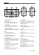
STUDIO WIZARD
QUICK SETUP
Initial Setup
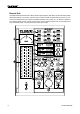
1. Turn all power to the Studio Wizard off. To
fully ensure this, disconnect the AC cable.
2.
Connect the Studio Wizard remote unit to the
main unit using the supplied RJ-45 cable.
3.
Connect your desired inputs to the Analog
Inputs on the rear of the main unit.
4.
If you have any products with S/PDIF or
AES/EBU capabilities, you can connect the
product’s S/PDIF output to the Studio Wiz-
ard’s S/PDIF or AES inputs.
5.
Depending on your requirements, you may
wish to connect monitors to each of the Stu-
dio Wizard’s outputs, or you may wish to
connect an amplier and speakers; it’s really
up to you.
6.
Connect any suitable recording devices
(tape recorders, or even laptop computers)
to the Record outputs of the Studio Wizard.
7.
Plug the supplied AC power cable into the AC
power connector on the main unit, and the
other end into a suitable AC power source.
Level Setting
1. With all your inputs and outputs connected
to the Studio Wizard, turn the unit on.
2.
Turn the level control knobs in the Studio
Select section to the 0 position (indicated in
the numeric display).
3.
Send a signal into any of the 6 digital and
analog inputs (similar to the input that will
usually be fed into that input), and feed that
input through to the currently selected output
and speaker (check signal routing, if a prob-
lem occurs).
4.
Adjust the trim control of the correspond-
ing input, on the front of the Studio Wizard’s
main unit, so that the signal level sits around
or slightly above the 0 mark on the remote
unit’s trim control.
5.
Now go and repeat the process with other
inputs. This should give you the best use of
audio from each input.
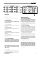
Signal Routing
1. Choose the output you wish to route any
signal to from the Studio Select area of the
remote unit. This could include the Record
1 and 2, Studio 1 and 2, and Head Phone
1 and 2 outputs. In this example, let’s say
you want to route the signal to the Record
1 outputs. Hold the Rec 1 button down for a
couple of seconds to enter Group Settings
Mode.
2.
The LEDs in the Input Select buttons sec-
tion should start ashing red. Press any of
these buttons to stop the LED ashing and
affectively remove it from your Group Set-
ting.
3.
Press the Rec 1 button again to exit Group
Setting mode.
4.
In the Input Select section, the LEDs of the
inputs removed from your Group Setting
should be off. The others should be red,
with exception to the signal that is currently
sent to the Record 1 output, which should
be blue. You can push any of the other In-
put Select buttons with red LEDs to send
that signal instead, if you’d rather.
5.
To send all of the inputs from your Group
Setting to the Record 1 output, you can
now press the Sum button. All the red
LEDs should then turn blue, and all the cor-
responding signals should be routed to the
Record 1 output.