
User Manual


6 STUDIO WIZARD
Main Unit
The main unit of the Studio Wizard can be placed
in a typical audio rack with the rest of your gear
(ampliers, equalizers, etc). On this unit you will
nd all of the Studio Wizards inputs and outputs,
as well as trim controls ensuring that audio lev-
els of the different inputs (and outputs) are not
excessive. In any permanent set up, you may
be able to plug your inputs and outputs into the
Studio Wizard’s main unit and leave it alone
from then on – all control over your audio can be
achieved through the remote unit.
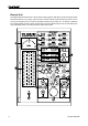
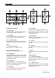
FRONT PANEL
1. Talkback Select Switch
This three-position switch allows users to se-
lect the built-in talkback microphone (or micro-
phones) they most wish to use: the internal, the
external, or both – simultaneously.
The internal microphone is located on the table-
top remote controller, whereas the external can
be connected to the talkback mic input just to the
right of this switch.
2. Talkback Phantom Power Button
Press this button to activate +48VDC of phantom
power for the external talkback microphone con-
nected to the Studio Wizard. Use phantom pow-
er when a condenser microphone (that requires
a +48V boost) is connected to the talkback mi-
crophone input. When phantom power is active,
the small LED inside the button lights up.
3. Talkback Microphone Input
This XLR-type input accepts balanced mic-level
signals from most dynamic and condenser mi-
crophones and is used it to connect an external
talkback microphone. Phantom power should be
activated when using condenser microphones.
4. Stereo 4 Inputs (RCA)
These RCA inputs accept unbalanced line-level
signals from CD players, tape decks and other
consumer audio devices.
5. Internal and External Talkback Controls
These two recessed trim level controls adjust the
gain level of the internal and external talkback
microphones.
6. Stereo Input Trim Controls
These recessed trim level controls adjust the
gain level of the four stereo analog inputs. Use
a small athead screwdriver or similar tool to ad-
just the levels. Turning these controls all the way
to the left will affectively mute the signal.
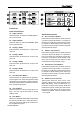
7. Tone Generator
The tone generator produces a continuous test
signal (tone) for use with real-time spectrum
analyzers when setting up the audio system.
Push the included button to toggle through the
test signals in the following order: 100 Hz 1
kHz 10 kHz Pink Noise. When a test tone
is active, it will be indicated by a small LED next
to the corresponding tone name. Push the Tone
Generator button on the remote unit to activate
the Tone Generator.
8. Speaker Trim Controls
These recessed trim level controls are used to
individually adjust the output level sent to each
set of speakers – the main, alternate, and mini.
HINT: Use a small athead screwdriver or even your nger-
nail to adjust the levels on recessed level controls.
9. Headphone Out 2
This 1/4" TRS output sends a stereo signal, ideal
for use with headphones when monitoring.
10. Remote Active Indicator
This LED indicator illuminates when the tabletop
remote control unit is connected.
11. Power Switch
This switch turns the power of the unit on and
off. When the unit is activated, the button will
illuminate blue.