
Installation & Assembly

B
A
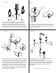
Connect stainless steel flex lines (9) from valve outlets to
spout tee (7). Flex lines should be looped as shown in
diagram. FLEX LINES MUST NOT BE KINKED. Adjust
valves and or spout teeto eliminate any kinking in the flex
lines. Install escutcheons onto the valves and hand tighten.
DO NOT OVER-TIGHTEN. Install handles onto valve stems.
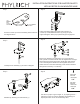
Insert drain plug (19) into drain assembly and insert ball rod
(18) as shown. Attach pop-up rod extension (15) to horizontal
ball rod (18) with “V” clip (17). Attach pop-up rod extension
to pop-up rod. To secure drain plug install the ball rod (18)
through the bottom hole (21) as shown in diagran “B”. To
install the drain plug so that it may be removed, place the
drain plug (21) on top of the ball rod (18). Adjust the height
of the drain plug (19) and pop-up rod extension so that the
basin both seals and drains adequately. Tighten pop-up rod
extension to secure assembly.
THIS STEP MUST BE COMPLETED TO ADHERE TO
THE LIMITED LIFETIME WARRANTY.
Flush hot and cold supply lines before connecting faucet
to supply lines. Connect the supplies to the bottom of the
lavatory valves using the brass coupling nuts provided or
with a flexible line. Connect your waste P-trap to the
drain tail piece.
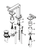
Insert drain rim (10) into the basin placing the Teflon washer
(11) under the rim. From below slip on washer (12) onto the
bottom thread of the drain rim and secure to basin with drain
nut and washer (13 and 14).
Step 7 Step 8
Step 9 Step 10
8
15
16
17
18
18
18
19
19
20
20
21
21
1-1/4”
Hole Diameter
*NOT SUPPLIED
*NOT SUPPLIED
* SUPPLY LINES AND ANGLE STOPS NOT INCLUDED
9
9
10
11
12
13
14