SERVICE STATION MANUAL 633823 MP3 250 i.e.
SERVICE STATION MANUAL MP3 250 i.e. The descriptions and illustrations given in this publication are not binding. While the basic specifications as described and illustrated in this manual remain unchanged, PIAGGIO-GILERA reserves the right, at any time and without being required to update this publication beforehand, to make any changes to components, parts or accessories, which it considers necessary to improve the product or which are required for manufacturing or construction reasons.
SERVICE STATION MANUAL MP3 250 i.e. This service station manual has been drawn up by Piaggio & C. Spa to be used by the workshops of Piaggio-Gilera dealers. It is assumed that the user of this manual for maintaining and repairing Piaggio vehicles has a basic knowledge of mechanical principles and vehicle repair technique procedures. Any significant changes to vehicle characteristics or to specific repair operations will be communicated by updates to this manual.
INDEX OF TOPICS CHARACTERISTICS CHAR TOOLING TOOL MAINTENANCE MAIN TROUBLESHOOTING TROUBL ELECTRICAL SYSTEM ELE SYS ENGINE FROM VEHICLE ENG VE ENGINE ENG INJECTION INJEC SUSPENSIONS SUSP BRAKING SYSTEM BRAK SYS COOLING SYSTEM COOL SYS CHASSIS PRE-DELIVERY TIME CHAS PRE DE TIME
INDEX OF TOPICS CHARACTERISTICS CHAR
Characteristics MP3 250 i.e. This section describes the general specifications of the vehicle. Rules This section describes general safety rules for any maintenance operations performed on the vehicle. Safety rules - If work can only be done on the vehicle with the engine running, make sure that the premises are wellventilated, using special extractors if necessary; never let the engine run in an enclosed area. Exhaust fumes are toxic. - The battery electrolyte contains sulphuric acid.
MP3 250 i.e. Characteristics Vehicle identification Chassis prefix (FULL OPTIONAL): M47201 Chassis prefix (BASE): M47200 Engine prefix: M472M Dimensions and mass WEIGHTS AND DIMENSIONS Specification Kerb weight Wheelbase Height Width (handlebar) Overall length Track Desc./Quantity 224 ± 5 Kg 1490 mm 1245 mm 745 mm 2130 mm 420 mm Engine DATA Specification Type Desc.
MP3 250 i.e. Characteristics Specification Timing system Bore Stroke Cubic capacity Compression ratio Air filter Starting system Lubrication Fuel supply valve clearance Engine idle speed Max. speed Desc./Quantity single overhead camshaft chain driven on the lefthand side, three-arm rocking levers set up with threaded set screw 72 mm 60 mm 249.29 mm 10.5 ÷ 11.
MP3 250 i.e. Characteristics Frame and suspensions FRAME AND SUSPENSIONS Specification Chassis Rear suspension Desc./Quantity Tubular and sheet steel. Single arm with two double-acting hydraulic shock absorbers and preloading adjustable to 4 positions. The tilt mechanism is composed of an articulated parallelogram suspension with die-cast aluminium control arms and two side headstocks plus shock absorbers with hydraulic locking system. Front suspension Brakes BRAKES Specification Front brake Desc.
MP3 250 i.e.
MP3 250 i.e. Characteristics Name Screw tightening calliper to the support Calliper upper pipe fitting Torque in Nm 20 ÷ 25 20 ÷ 25 REAR BRAKE Name Rear brake disc screws(°) Rear brake calliper-pipe fitting Rigid / flexible pipe fitting Rear brake pump-pipe fitting Rear brake calliper fixing screws Torque in Nm 5 ÷ 6.
MP3 250 i.e.
MP3 250 i.e. Characteristics Cylinder - piston assy. ENGINE COUPLING CATEGORY Name Cylinder Cylinder Piston Piston Initials M N O P Cylinder 72.01 ÷ 72.017 72.017 ÷ 72.024 72.024 ÷ 72.031 72.031 ÷ 72.038 Piston 71.953 ÷ 71.960 71.960 ÷ 71.967 71.967 ÷ 71.974 71.974 ÷ 71.981 Play on fitting 0.050 - 0.064 0.050 - 0.064 0.050 - 0.064 0.050 - 0.064 Crankcase - crankshaft - connecting rod CRANKSHAFT Titolo Durata/Valore Crankshaft Testo Breve (< 4000 car.
MP3 250 i.e. Characteristics CRANKSHAFT/ CRANKCASE AXIAL CLEARANCE Name Half-shaft, transmission side Flywheel-side halfshaft Connecting rod Spacer tool Description Slot packing system Characteristic Compression ratio 10.5 ÷ 11.5 : 1 CHAR - 10 Dimensions 16.6 +0-0.05 Initials A Quantity D = 0.20 - 0.50 16.6 +0-0.05 B D = 0.20 - 0.50 18 -0.10 -0.15 51.4 +0.05 C E D = 0.20 - 0.50 D = 0.20 - 0.
MP3 250 i.e. Characteristics Measurement "A" to be taken is a value of piston re-entry, it indicates by how much the plane formed by the piston crown falls below the plane formed by the top of the cylinder. The further the piston falls inside the cylinder, the less the base gasket to be applied (to recover the compression ratio) and vice versa. N.B.
MP3 250 i.e.
INDEX OF TOPICS TOOLING TOOL
MP3 250 i.e.
MP3 250 i.e.
MP3 250 i.e.
MP3 250 i.e.
MP3 250 i.e.
MP3 250 i.e.
MP3 250 i.e.
MP3 250 i.e.
MP3 250 i.e.
MP3 250 i.e.
MP3 250 i.e.
MP3 250 i.e.
Tooling TOOL - 14 MP3 250 i.e.
INDEX OF TOPICS MAINTENANCE MAIN
MP3 250 i.e. Maintenance Follow these steps to reset the service icons: 1. With the key set to OFF, hold down the "SET" button and turn the key to ON : the "BELT" and "SERVICE" icons start flashing. 2. Push the "CLOCK" button for less than 1 second and the icons are displayed sequentially. The icon selected remains ON and the other is no longer displayed. 3. Press the "CLOCK" button again for more than 3 seconds to reset the relative maintenance step and the icon is no longer displayed.
MP3 250 i.e.
MP3 250 i.e.
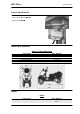
MP3 250 i.e. Maintenance - Remove the transmission crankcase. - Rotate the driving pulley fan until the reference marks between the flywheel and flywheel cover coincide as shown in the photograph. - Bring the reference mark onto the transmission side between the fan and the transmission cover as shown in the photograph. - Refit the spark plug. - Refit the plastic cap on the flywheel cover.
Maintenance Spark plug Remove the port on the right-hand side panel of the vehicle by undoing the clamping screw and using a small screwdriver in the rear recess shown in the figure, then do the following : 1. Disconnect spark plug HV wire cap "A"; 2. Unscrew the spark plug using the wrench supplied. ; 3. When refitting, place the spark plug in the hole at the due inclination and tighten it by hand until it is finger tight; 4. Only use the wrench to lock it in place; 5.
MP3 250 i.e. Maintenance CHAMPION RG4 PHP Electrode gap 0.7 ÷ 0.8 mm Hub oil Check - Park the vehicle on its centre stand on flat ground; - Remove the oil dipstick «A», dry it with a clean cloth and put it back into its hole tightening it completely; Remove the dipstick and check that the oil level is slightly over the second notch starting from the lower end; if the level is under the MAX. mark, it needs to be filled with the right amount of hub oil.
Maintenance MP3 250 i.e. Air filter Proceed as follows: Undo the clamping screws «A» (two of which are on the knob-type head) and remove the air-box cover. 1. Wash the sponge with water and neutral soap. 2. Dry it with a clean cloth and small blasts of compressed air. 3. Impregnate the sponge with a mixture of 50% petrol and 50% specified oil. 4. Gently squeeze the filter element, let it drip and then refit it.
MP3 250 i.e. Maintenance Make sure the pre-filter and discharge tap O-rings are in good condition. Lubricate them and refit the gauze filter and oil drainage tap, screwing them up to the specified torque. Refit the new cartridge filter being careful to lubricate the O-ring before fitting it. Change the engine oil. Since a certain quantity of oil still remains in the circuit, oil must be filled from cap "A".
Maintenance MP3 250 i.e. The MAX level mark indicates a quantity of around 1300 cc of engine oil. If the check is carried out after the vehicle has been used, and therefore with a hot engine, the level line will be lower; in order to carry out a correct check it is necessary to wait at least 10 minutes after the engine has been stopped, so as to get the correct level. Oil top up The oil should be topped up after having checked the level and in any case by adding oil without ever exceeding the MAX. level.
MP3 250 i.e. Maintenance Checking the ignition timing -Remove the plastic cap on the flywheel cover -Turn the flywheel until the reference mark «T» on the rotor matches the reference mark on the flywheel cover as shown in the figure (TDC). Make sure that the 4V reference point on the camshaft control pulley is aligned with the reference point on the head as shown in the second figure. If the reference is opposite the indicator on the head, turn the crankshaft once more.
Maintenance Braking system Level check The front and rear brake fluid reservoirs are both positioned on the handlebars. Proceed as follows: - Rest the vehicle on its centre stand with the handlebars perfectly horizontal; - Check the fluid level through the sight glass «C». A certain lowering of the level is caused by wear on the pads. Top-up Proceed as follows: Loosen the screw "B" and lift the plastic cover "A" in order to access the brake fluid reservoir.
MP3 250 i.e. Maintenance Headlight adjustment Proceed as follows: 1. Position the unloaded vehicle, in running order and with the tyres inflated to the prescribed pressure, on a flat surface 10 m away from a half-lit white screen; ensure that the longitudinal axis of the vehicle is perpendicular to the screen; 2. Remove the headlight assembly central cover 3.
Maintenance MAIN - 14 MP3 250 i.e.
INDEX OF TOPICS TROUBLESHOOTING TROUBL
MP3 250 i.e. Troubleshooting This section makes it possible to find what solutions to apply when troubleshooting. For each breakdown, a list of the possible causes and respective interventions is given.
MP3 250 i.e. Troubleshooting Insufficient braking INEFFICIENT BRAKING SYSTEM Possible Cause Inefficient braking system Fluid leakage in hydraulic braking system Brake disc slack or distorted Operation Check the pad wear (1.5 min). Check that the brake discs are not worn, scored or warped. Check the correct level of fluid in the pumps and replace brake fluid if necessary. Check there is no air in the circuits; if necessary, bleed the air. Check that the front brake calliper moves in axis with the disc.
MP3 250 i.e. Troubleshooting Possible Cause Operation if they are recessed or if the balls are squashed, replace them. Noisy suspension NOISY SUSPENSION Possible Cause Malfunctions in the suspension system Operation If the front suspension is noisy, check: the efficiency of the front shock absorbers; the condition of the ball bearings and relevant lock-nuts, the limit switch rubber buffers and the movement bushings.
INDEX OF TOPICS ELECTRICAL SYSTEM ELE SYS
Electrical system KEY 1. Immobilizer aerial 2. Injection ECU 3. Engine rev sensor 4. Magneto flywheel 5. Diagnostics socket 6. Voltage regulator 7. Key switch 8. Fuse-box 9. Fuse-box 10. Battery 11. Starter motor 12. Start up remote control switch 13. Starter button 14. Stop button on front brake 15. Stop button on rear brake 16. Helmet compartment light switch 17. Helmet compartment light switch 18. Helmet compartment light bulb 19. Saddle opener actuator 20.
MP3 250 i.e. Electrical system 21. Preparation for anti-theft device 22. Turn indicator switch 23. Hazard switch 24. Turn indicator control device 25. Left rear turn indicator bulbs 26. Rear headlight assembly A. Tail light C. Stop light 27. License plate bulb 28. Right rear turn indicator bulbs 29. Left front turn indicator bulb 30. Front headlight assembly A. Low-beam light bulb B. Tail light C. High-beam light bulb 31. Right front turn indicator bulb 32. Light switch 33. Remote control headlight 34.
Electrical system 54. Engine stop switch 55. Mode button 56. Engine temperature sensor 57. Fuel pump 58. Fuel injector 59. Lambda probe 60. Spark plug 61. High voltage coil Key Ar: Orange Az: Sky blue Bi: White Bl: Blue Gi: Yellow Gr:Grey Ma:Brown Ne: Black Ro: Pink Rs: Red Ve: Green Vi: Purple Electrical system installation ELE SYS - 4 MP3 250 i.e.
MP3 250 i.e.
Electrical system ELE SYS - 6 MP3 250 i.e.
MP3 250 i.e.
Electrical system ELE SYS - 8 MP3 250 i.e.
MP3 250 i.e.
Electrical system Conceptual diagrams Ignition KEY 1. Immobilizer aerial 2. Injection ECU 3. Revolution sensor 7. Key switch 8. Fuse-box 9. Fuse-box 10. Battery ELE SYS - 10 MP3 250 i.e.
MP3 250 i.e. Electrical system 53. Injection load remote control 60. Spark plug 61. High voltage coil Battery recharge and starting KEY 2. Injection ECU 4. Magneto flywheel 6. Voltage regulator 7. Key switch 8. Fuse-box 9. Fuse-box 10. Battery 11. Starter motor 12. Start up remote control switch 13. Starter button 14. Stop button on front brake 15. Stop button on rear brake 26. Rear headlight assembly B. Stop light 54.
Electrical system Level indicators and enable signals section KEY 1. Immobilizer aerial 2. Injection ECU 3. Revolution sensor 7. Key switch 8. Fuse-box 9. Fuse-box 10. Battery 38. Locking/unlocking switch 39. Geared motor 40. Right tone wheel 41. Left tone wheel 42. Brake calliper sensor 43. Parking electronic control unit 44. Oil pressure sensor 45. Hand brake 46. Rider presence sensor 47. Potentiometer 48. Instrument panel ELE SYS - 12 MP3 250 i.e.
MP3 250 i.e. Electrical system 49. External temperature sensor 50. Fuel level transmitter 53. Injection load remote control 54. Engine stop switch 55. Mode button 56. Engine temperature sensor 57. Fuel pump 58. Fuel injector 59. Lambda probe Devices and accessories KEY 2. Injection ECU 7. Key switch 8. Fuse-box 9. Fuse-box 10. Battery 19. Saddle opening actuator 20. Saddle opening receiver 21. Wiring for antitheft device 34.
Electrical system 35. Horn 36. Horn button 37. Pressure sensor 43. Parking electronic control unit 51. Electric fan 52. Remote control for electric fan Lights and turn indicators KEY 7. Key switch 8. Fuse-box 9. Fuse-box 10. Battery 21. Wiring for antitheft device 22. Turn indicator switch 23. Hazard switch 24. Turn indicator control device 25. Left rear turn indicator bulbs 26. Rear headlight assembly A. Tail light B. Stop light ELE SYS - 14 MP3 250 i.e.
MP3 250 i.e. Electrical system 27. License plate bulb 28. Right rear turn indicator bulbs 29. Left front turn indicator bulb 30. Front headlight assembly A. Low-beam light bulb B. Tail light C. High-beam light bulb 31. Right front turn indicator bulb 32. Light switch 33. Remote control headlight 43. Parking electronic control unit 48. Instrument panel Checks and inspections This section is devoted to the checks on the electrical system components.
Electrical system ignition switch is turned to the "OFF" position, or the emergency stop switch is turned to the "OFF" position. It remains activated for 48 hours in order not to affect the battery charge. When the ignition switch is turned to the "ON" position, the deterring blinker function is deactivated. Subsequently, a flash confirms the switching to the "ON" status.
MP3 250 i.e. • Electrical system There is continuity between terminals 12-18 and 12-19 with the emergency cut-out switch in the RUN position. If there is no continuity check the contacts of the latter. If no faults are found, replace the electronic control unit. After removing the shield back plate, remove the electrical connection from the aerial as shown in the photograph Remove the protective base from the connector.
Electrical system MP3 250 i.e. With MIU connector disconnected check the continuity between the Orange-White cable and pin 7 of the interface wiring . Specific tooling 020481Y Control unit interface wiring 020331Y Digital multimeter Virgin circuit When the ignition system is not encrypted, any key will start the engine but limited to 2000 rpm. The keys can only be recognised if the control unit has been programmed properly.
MP3 250 i.e. Electrical system Characteristic MASTER key: RED KEY SERVICE key. BLACK KEY Diagnostic codes The immobiliser system is tested each time the ignition-key switch is turned from OFF to ON. During this diagnosis phase a number of control unit statuses can be seen and various light codes displayed. Regardless of the code transmitted, if at the end of the diagnosis the led remains off permanently, the ignition is enabled.
Electrical system MP3 250 i.e. LED remains permanently OFF. The engine can be started. 5. Programmed control unit - fault detected: a light code is displayed according to the fault detected, after which the LED remains on permanently. The engine cannot be started. The codes that can be transmitted are: • Code 1 flash • 2 flash code • 3 flash code Diagnostic code - 1 flash The one-flash code indicates a system where the serial line is not present or is not detected.
MP3 250 i.e. Electrical system Diagnostic code - 3 flashes The three-flash code indicates a system where the control unit does not recognise the key. Turn the switch to ON using several keys: if the error code is repeated even with the Master key, replace the control unit. If this is not the case, perform a reprogramming. Battery recharge circuit The recharge system is provided with a three-phase alternator with permanent magneto flywheel. The alternator is directly connected to the voltage regulator.
MP3 250 i.e. Electrical system 4) Check that there is insulation between the each yellow cable and the ground. 5) If values are incorrect, replace the stator. Recharge system voltage check Look for any leakage 1) Access the battery by removing its cover under the saddle. 2) Check that the battery does not show signs of losing fluid before checking the output voltage.
MP3 250 i.e. Electrical system Fuses The electrical system has twelve fuses divided in two fuse boxes to protect the different installation circuits. One of them is inside the battery compartment and the other is at the right internal side of the footrest. To be able to reach, loosen the screw "A" and remove the plastic cover. The chart shows the position and characteristics of the fuses in the vehicle. CAUTION BEFORE REPLACING THE BLOWN FUSE, FIND AND SOLVE THE FAILURE THAT CAUSED IT TO BLOW.
MP3 250 i.e. Electrical system 7 Specification Fuse No. 7 8 Fuse No. 8 9 Fuse No. 9 10 Fuse No. 10 11 Fuse No. 11 12 Fuse No. 12 Desc./Quantity Capacity: 7.5 A Protected circuits:Battery-powered instrument panel Location:footrest Capacity: 10A Protected circuits:Live stop and start lights Location:footrest Capacity: 7.5 A Protected circuits:live passing and horn Location:battery compartment Capacity: 7.
MP3 250 i.e.
Electrical system -Initial charge voltage equal to 0.3 ÷ 0.
MP3 250 i.e.
Electrical system MP3 250 i.e. Zeroing - Remove the left side fairing to access the saddle opening receiver control unit indicated in the photograph - Remove the metal terminal and connect it to a good earth point, or to terminal 7 (black), for at least 10 seconds. - In this operation all the remote controls stored in the control unit will be deleted. WARNING THE CONTROL UNIT CAN PROGRAMME UP TO 8 REMOTE CONTROLS. Programming Follow these steps to program the remote controls: 1.
MP3 250 i.e. Electrical system TO AVOID BATTERY DISCHARGE, THE SADDLE OPENING REMOTE CONTROL RADIO RECEIVER DEACTIVATES 7 DAYS AFTER THE LAST TIME THE VEHICLE WAS SHUT OFF. JUST TURN THE KEY TO «ON» TO REACTIVATE THE RECEIVER.
Electrical system ELE SYS - 30 MP3 250 i.e.
INDEX OF TOPICS ENGINE FROM VEHICLE ENG VE
Engine from vehicle MP3 250 i.e. This section describes the operations to carry out when removing the engine from the vehicle. Exhaust assy. Removal - Remove the Lambda probe from its support and disconnect it. - Undo the two exhaust manifold fixings on the head.
MP3 250 i.e. Engine from vehicle CAUTION: SHOULD IT BE NECESSARY TO REMOVE ONLY THE MUFFLER TIP, ALWAYS REPLACE THE GRAPHITE GASKET BETWEEN STUB AND TIP. Removal of the engine from the vehicle - Disconnect the battery - Remove the engine cover inside the helmet compartment - Remove the side panels Remove the full muffler assembly. CAUTION THIS OPERATION MUST BE CARRIED OUT WHEN THE ENGINE IS COLD. - Remove the rear wheel.
Engine from vehicle - Remove the coolant outlet pipe from the motor as indicated. - Remove the spark plug caps. - Remove the coolant temperature sensor connector indicated in the photo. - Remove the throttle cable from the throttle body by undoing the nut shown in the photo. - Remove the positive and negative wiring from the starter motor as shown in the photo. ENG VE - 4 MP3 250 i.e.
MP3 250 i.e. Engine from vehicle - Disconnect the connectors from the flywheel wiring as shown in the photo. - Remove the cable from the retaining clip on the flywheel cover. Remove the lower screw of the left-hand shock absorber. - Use a jack to support the vehicle properly. Remove the engine-swinging arm fixing pin by undoing the nut and the head of the pin as shown in the photograph. - The engine is now free.
Engine from vehicle MP3 250 i.e. PAY PARTICULAR ATTENTION TO POSITIONING THE THROTTLE COMMAND TRANSMISSION PROPERLY.
INDEX OF TOPICS ENGINE ENG
Engine MP3 250 i.e. This section describes the operations to be carried out on the engine and the tools to be used. Automatic transmission Transmission cover - To remove the transmission cover it is necessary to remove the plastic cover first, by inserting a screwdriver in the slotted holes. Using the clutch bell lock wrench shown in the figure, remove the driven pulley shaft locking nut and washer.
MP3 250 i.e. Engine - To remove the intake throat on the transmission cover, just remove the 2 fixing screws indicated in the figure. Removing the driven pulley shaft bearing - Remove the clip from the inside of the cover. - Remove the bearing from the crankcase by means of: Specific tooling 020376Y Adaptor handle 020375Y Adaptor 28 x 30 mm 020412Y 15 mm guide Refitting the driven pulley shaft bearing - Slightly heat the crankcase from the inside so as not to damage the painted surface.
Engine Plastic roller - Check that the roller does not show signs of wear and that it turns freely. - Remove the special clamping screws as indicated in the photograph - Check the outer diameter of the roller does not have defects that could jeopardise belt functioning - For refitting, place the roller with the belt containment edge on the engine crankcase side - Tighten the wrench to the prescribed torque.
MP3 250 i.e. Engine Inspecting the clutch drum - Check that the clutch bell is not worn or damaged. - Measure the clutch bell inside diameter. Characteristic Max. value clutch bell Max. value: Ø 134.5 mm Clutch bell standard value Standard value: Ø 134 - 134.2 mm Checking the bell working surface eccentricity - Install the bell on a driven pulley shaft using 2 bearings (inner diameter 15 and 17 mm). - Lock with the original spacer and nut.
Engine Removing the clutch Fit the driven pulley spring compressor specific tool with medium length pins screwed in position «C» on the tool internal side. - Introduce the adapter ring No. 11 with the chamfering facing the inside of the tool. - Fit the driven pulley unit on the tool with the insertion of the 3 pins in the ventilation holes in the mass holder support. - Make sure that the clutch is perfectly inserted into the adapter ring before proceeding to loosen/tighten the clutch nut.
MP3 250 i.e. Engine DO NOT OPEN THE MASSES USING TOOLS TO PREVENT A VARIATION IN THE RETURN SPRING LOAD. Characteristic Check minimum thickness 1 mm Pin retaining collar - Simultaneously turn and pull the collar manually to remove it. N.B. USE TWO SCREWDRIVERS IF YOU HAVE DIFFICULTY. N.B. BE CAREFUL NOT TO PUSH THE SCREW DRIVERS IN TOO FAR TO AVOID DAMAGE THAT COULD ENDANGER THE O-RING SEAL. - Remove the four torque server pins and pull the pulley halves apart.
Engine - Support the pulley properly using the bell as shown in the figure. Specific tooling 001467Y035 Belle for OD 47-mm bearings - Remove the roller bearing using the modular punch. Specific tooling 020376Y Adaptor handle 020456Y Ø 24 mm adaptor 020363Y 20 mm guide Inspecting the driven fixed half-pulley Version 250 - Measure the outer diameter of the pulley bushing. - Check the contact surface with the belt to make sure there are no flaws. - Check the riveted joints are functional.
MP3 250 i.e. Engine Inspecting the driven sliding half-pulley - Remove the two internal grommets and the two O-rings. - Measure the movable half-pulley bushing inside diameter. - Check the contact surface with the belt to make sure there are no flaws. - Check the riveted joints are functional. - Check the evenness of the belt faying surface. MOVABLE DRIVEN HALF-PULLEY DIMENSIONS Specification Wear limit standard diameter maximum allowable diameter Desc./Quantity 0.3 mm Diameter 41.000 - 41.035 mm Ø 41.
Engine Refitting the driven pulley - Insert the new oil guards and O-rings on the movable half-pulley. - Lightly grease the O-rings «A» shown in the figure. - Fit the half-pulley over the bushing using the specific tool. - Check that the pins are not worn and proceed to refitting them in their slots. - Refit the torque server closure collar. - Using a curved-spout grease gun, lubricate the driven pulley unit with approximately 6 gr. of grease.
MP3 250 i.e. Engine Soap-based lithium grease containing NLGI 2 Molybdenum disulphide; ISO-L-XBCHB2, DIN KF2K-20 Inspecting the clutch spring - Measure the length of the spring, while it is relaxed. Characteristic Standard length 123 mm acceptable limit after use: 118 mm Refitting the clutch - Support the driven pulley spring compressor appropriate tool with the control screw in vertical axis. - Arrange the tool with the medium length pins screwed in position "C" on the inside.
Engine - Apply the clutch fixing nut and tighten it to the prescribed torque using the special 46x55 wrench. - Loosen the tool clamp and insert the belt according to its direction of rotation. - Lock the driven pulley again using the specific tool. - Preload the clutch return spring with a traction/ rotation combined action and place the belt in the smaller diameter rolling position. - Remove the driven pulley /belt unit from the tool. N.B.
MP3 250 i.e. Engine Drive-belt - Check that the driving belt is not damaged. - Check the width of the belt. Characteristic 250 4T Transmission belt/minimum width 19.5 mm 250 4T Transmission belt/standard width 21.3 ± 0.2 mm During the wear checks in the scheduled servicing programme, you are advised to check the rim bottom of the toothing does not show signs of incisions or cracking (see figure): The rim bottom of the tooth must not have incisions or cracking; if it does, change the belt.
Engine - Insert the tool in the hollows and apply the retention ring - Bring in the ring's clamping screws while keeping the tool to support the pulley Specific tooling 020626Y Driving pulley lock wrench - Remove the fixing nut and the washer - Remove the stationary drive pulley half. Inspecting the rollers case - Check that the internal bushing shown in the figure is not abnormally worn and measure inner diameter A. - Measure outer diameter B of the pulley sliding bushing shown in the figure.
MP3 250 i.e. Engine 26.000 - 26.021 mm Movable driving half-pulley bushing: Maximum allowable diameter Ø 26.12 mm Sliding bushing: Standard Diameter Ø 25.959 ÷ 25.98 mm Sliding bushing: Minimum admissible diameter Ø 25.95 mm Roller: Standard Diameter Diameter 20.5 - 20.
Engine - Fit the steel shim in contact with the bushing and the stationary drive pulley. - Install the appropriate tool as described in the removal phase. -Tighten the nut with washer to the prescribed torque. Specific tooling 020626Y Driving pulley lock wrench Locking torques (N*m) Drive pulley nut 75 ÷ 83 Refitting the transmission cover - Check the presence of the 2 centring dowels and the correct installation of the sealing gasket for the oil sump on the transmission cover.
MP3 250 i.e. Engine Removing the hub cover - Empty the rear hub through the oil drainage plug. - Remove the 7 flanged screws indicated in the figure. - Remove the hub cover and its gasket. Removing the wheel axle - Remove the wheel axis complete with gear. - Remove the intermediate gear.
Engine Removing the hub bearings - Check the state of the bearings being examined (wear, clearance and noisiness). If faults are detected, do the following. - Use the specific bearing extractor to remove the three 15 mm bearings (2 in the crankcase and 1 in the hub cover). Specific tooling 001467Y013 Pliers to extract ø 15-mm bearings Removing the wheel axle bearings - Take out the clip on the outside of the gearbox cover. - Support the hub cover and expel the bearing.
MP3 250 i.e. Engine Removing the driven pulley shaft bearing - As you need to remove the driven pulley shaft, its bearing and oil guard, remove the transmission cover as described above. - Extract the driven pulley shaft from its bearing. - Remove the oil guard using a screwdriver, working from inside the bearing and being careful not to damage the housing, make it come out of the belt transmission side.
Engine Refitting the wheel axle bearing - Support the hub cover on a wooden surface. - Heat the crankcase cover with the specific heat gun. - Fit the wheel shaft bearing with a modular punch as shown in the figure. - Fit the seeger ring. - Fit the oil guard with seal lip towards the inside of the hub and place it flush with the internal surface by means of the appropriate tool used from the 52 mm side. The 52 mm side of the adapter must be turned towards the bearing.
MP3 250 i.e. Engine Refitting the hub cover bearings For the fitting of the hub box bearings the engine crankcase and the cover must be heated with the special heat gun. - The three 15 mm bearings must be fitted using the appropriate tools. - The 42-mm side of the adapter must be turned towards the bearing. Specific tooling 020150Y Air heater support 020151Y Air heater 020376Y Adaptor handle 020359Y 42x47-mm adaptor 020412Y 15 mm guide N.B.
Engine Refitting the hub bearings - Install the three shafts in the engine crankcase as shown in the figure. Refitting the ub cover - Fit a new gasket together with the centring dowels. - Seal the gasket of the breather pipe using black silicone sealant. - Fit the gearbox cover, making sure the breather pipe is in the correct position. - Position the shorter screw that can also be recognised from the different colour as shown in the figure. - Fix the breather tube support by means of the lower screw.
MP3 250 i.e. Engine Removing the hub cover - Remove the clip fixing the hose to the cylinder. - Remove the ten fixings - Remove the flywheel cover. Removing the stator - Remove the two pickup screws and the screw holding the wiring support and the three stator clamping screws shown in the figure. - Remove the stator and its wiring.
Engine MP3 250 i.e. Refitting the stator - Refit the stator and flywheel carrying out the removal procedure in reverse, tightening the retainers to the specified torque. Locking torques (N*m) Stator assembly screws (°) 3 ÷ 4 Refitting the flywheel cover - Position the spline clip on the crankshaft and orient the end as shown in the figure. - Orient the water pump shaft with reference to the transmission gear seat as shown in the photo.
MP3 250 i.e. Engine Removing the starter motor - Remove the two screws indicated in the figure. - Take the starter motor out of its seat Removing the flywheel magneto - Remove the water pump shaft and crankshaft spline clip - Line up the two holes in the flywheel as shown in the photo - Screw in the guide bushing that is part of the special flywheel stop tool on the flywheel as shown in the photo.
Engine MP3 250 i.e. - Insert the special flywheel stop tool on the flywheel as shown in the photo Specific tooling 020627Y Flywheel lock wrench - Remove the plate indicated in the photo.
MP3 250 i.e. Engine - Fit the freewheel on the magneto flywheel making sure that the ground side is in contact with the flywheel itself, i.e. with wheel seeger ring visible. - Lock the six clamping screws in criss-cross fashion to the prescribed torque. Locking torques (N*m) Screw fixing freewheel to flywheel 13 ÷ 15 - Oil the free wheel "rollers".
Engine - Using the special flywheel stop tool, tighten up the flywheel fixing nut to the prescribed torque -Refit the retention plate Specific tooling 020627Y Flywheel lock wrench Locking torques (N*m) Flywheel nut 94 ÷ 102 Refitting the starter motor - Fit a new O-ring on the starter motor and lubricate it. - Fit the starter on the crankcase, locking the two screws to the prescribed torque. Locking torques (N*m) Starter motor screws 11 ÷ 13 Cylinder assy.
MP3 250 i.e. Engine Removing the rocker-arms cover - Remove the 5 screws indicated in the figure Removing the timing system drive - Remove the parts listed below first: transmission cover, drive pulley with belt, oil sump with spring and by-pass piston, oil pump pulley cover, O-ring on the crankshaft and the sprocket wheel separation washer. - Remove the tappet cover. - Remove the central screw fastener and the automatic valve-lifter retaining cover, as shown in the figure.
Engine - Loosen the central screw on the tensioner first. - Remove the two fixings shown in the figure. - Remove the tensioner with its gasket. - Remove the internal hex screw and the counterweight shown in the figure. - Remove the camshaft control pulley with its washer. - Remove the command sprocket wheel and the timing chain. - Remove the screws indicated in the figure, the spacer bar and the tensioner slider. The chain tensioning pad must be removed from the transmission side.
MP3 250 i.e. Engine Removing the cam shaft - Remove the two screws and the cam shaft retainer shown in the diagram. - Remove the cam shaft. - Remove the pins and the rocker arms from the flywheel side holes. N.B. IN CASE OF NEED, THE HEAD MAY BE REMOVED WITH THE CAMSHAFT, PINS, ROCKING LEVERS AND FIXING BRACKET. THE HEAD CAN ALSO BE REMOVED WITHOUT REMOVING THE CHAIN AND THE DRIVING SHAFT CHAIN TIGHTENER. Removing the cylinder head - Remove the spark plug.
Engine MOVING THE CHAIN AND THE DRIVING SHAFT CHAIN TIGHTENER. Removing the valves - Using the appropriate tool fitted with an adaptor, remove the cotters, caps, springs and valves. - Remove the oil guards with the appropriate tool. - Remove the lower spring supports. CAUTION REPLACE THE VALVES IN SUCH A WAY AS TO RECOGNISE THEIR ORIGINAL POSITION ON THE HEAD.
MP3 250 i.e. Engine Inspecting the small end - Measure the internal diameter of the small end using an internal micrometer. N.B. REPLACE THE CRANKSHAFT IF THE DIAMETER OF THE ROD SMALL END EXCEEDS THE STANDARD DIAMETER OR IT SHOWS SIGNS OF WEAR OR OVERHEATING. Characteristic Checking the connecting rod small end: Maximum diameter 15.030 mm Checking the connecting rod small end: Standard diameter 15 +0.015+0.025 mm Inspecting the wrist pin - Measure the outer diameter of the gudgeon pin.
Engine Inspecting the piston - Measure the diameter of the wrist pin seat on the piston. - Calculate the piston pin coupling clearance. - Measure the outside diameter of the piston, perpendicular to the gudgeon pin axis. - Take the measurement at 5 mm from the base in the position shown in the figure. - Carefully clean the seal housings. - Measure the coupling clearance between the seal rings and the grooves using suitable sensors, as shown in the diagram.
MP3 250 i.e. Engine Inspecting the cylinder - Using a bore meter, measure the inner cylinder diameter at three different points according to the directions shown in the figure. - Check that the head coupling surface is not worn or misshapen. - Pistons and cylinders are classified according to diameter. The coupling must be made with those of the same type (M-M, N-N, O-O, P-P). Characteristic cylinder: standard diameter 71.990 - 72.018 mm (at 33 mm) Maximum allowable run-out: 0.
Engine Sealing rings - Alternately insert the three sealing rings into the cylinder, in the area where it retains its original diameter. Using the piston, insert the rings perpendicularly to the cylinder axis. - Measure the opening (see figure) of the sealing rings using a feeler gauge. - If any measurements are greater than specified, replace the piston rings. N.B.
MP3 250 i.e. Engine THE TOOL FOR INSTALLING THE STOP RINGS MUST BE USED MANUALLY. CAUTION USING A HAMMER MIGHT DAMAGE THE STOPS' HOUSING. Specific tooling 020454Y Tool for fitting piston pin stops (200 250) Choosing the gasket Characteristic Compression ratio 250 version CR: 10.5 ÷ 11.5 : 1 N.B.
MP3 250 i.e. Engine THE TOP OF THE CYLINDER. THE FURTHER THE PISTON FALLS INSIDE THE CYLINDER, THE LESS THE BASE GASKET IS TO BE APPLIED (TO RECOVER THE COMPRESSION RATIO) AND VICE VERSA. ENGINE 250 SHIMMING Name shimming shimming shimming Measure A 3.70 - 3.60 3.60 - 3.40 3.40 - 3.30 Refitting the piston rings Fitting the sealing rings - Place the oil scraper spring on the piston.
MP3 250 i.e. Engine Refitting the cylinder - Insert the cylinder base gasket with the thickness determined above. - Using the fork support and the piston ring retaining band, refit the cylinder as shown in the figure. N.B. BEFORE FITTING THE CYLINDER, CAREFULLY BLOW OUT THE LUBRICATION DUCT AND OIL THE CYLINDER BARREL.
Engine Inspecting the timing system components - Check that the guide shoe and the tensioner shoe are not worn out. - Ensure that the camshaft control pulley chain assembly and the sprocket wheel are not worn. - If you encounter wear, replace the parts or, if the chain, sprocket wheel and pulley are worn replace the whole assembly. - Remove the centre screw with the washer and the tensioner spring. Check that the one-way mechanism is not worn. - Check the condition of the tensioner spring.
MP3 250 i.e. Engine Inspecting the valve housings - Check the width of the imprint on the valve seat«V» wear limit max. 1.6 mm. - Remove any carbon formation from the valve guides. - Measure the inside diameter of each valve guide. - Take the measurement at three different heights in the rocker arm push direction. - If the width of the impression on the valve seat or the diameter of the valve guide exceed the specified limits, replace the cylinder head.
Engine MP3 250 i.e. - Calculate the clearance between valve and valve guide. - Check that there are no signs of wear on the surface of contact with the articulated register terminal. - If the checks above give no failures, you can use the same valves. For best sealing results, it is advisable to grind the valves. Grind the valves gently with a fine-grained lapping compound. During the grinding, keep the cylinder head with the valve axes in a horizontal position.
MP3 250 i.e. Engine Inspecting the springs and half-cones - Check that the upper spring caps and the cotter halves show no signs of abnormal wear.
Engine Refitting the valves - Lubricate the valve guides with engine oil. - Place the valve spring supports on the head. - Using the special punch, fit the four valve seals. - Fit the valves, the springs and the caps. Using the appropriate tool with adapter, compress the springs and insert the cotters in their seats. N.B. DO NOT CHANGE THE VALVE FITTING POSITION. FIT THE VALVE SPRINGS WITH THE REFERENCE COLOUR ON COTTER SIDE (TURNS WITH GREATER PITCH).
MP3 250 i.e. Engine - Measure the internal diameter of each rocker arm. Check there are no signs of wear on the pad from contact with the cam and on the jointed adjustment plate. Characteristic Internal rocker arm diameter: Standard diameter Diameter 12.000 - 12.011 mm Rocker arm pin diameter: Standard diameter Diameter 11.977 - 11.985 mm Cam shaft check: Maximum admissible axial clearance 0.42 mm Cam shaft check: Standard axial clearance: 0.11 - 0.41 mm Cam shaft check: Standard height Outlet: 29.
Engine Refitting the head and timing system components - Fit the timing chain guide pad. - Insert the centring dowel between the cylinder head to the cylinder, fit the cylinder head gasket and the cylinder head. - Lubricate the stud bolt threading. - Tighten up the nuts to an initial pre-torque of 7±1 N·m - Tighten up the nuts to a second pre-torque of 10 ±1 N·m - Rotate by an angle of 270° - To carry out the operations described above, follow the tightening sequence in the figure.
MP3 250 i.e. Engine - Lubricate the 2 bearings and insert the cam shaft in the cylinder head with the cams corresponding to the rockers. - Insert the retention plate and tighten the two screws shown in the figure to the prescribed torque. - Refit the spacer on the cam shaft. - Rotate the engine so that the piston is at top dead centre, using the reference marks on the flywheel and the crankcase. - Holding this position insert the chain on the camshaft control pulley.
Engine GREASE THE END STOP RING TO PREVENT IT COMING OUT AND FALLING INTO THE ENGINE. Locking torques (N*m) Timing chain tensioner support screw 11 ÷ 13 Spark plug 12 ÷ 14 Starter ground screw 7 ÷ 8.5 Timing chain tensioner slider screw 10 ÷ 14 Starter ground support screw 11 ÷ 15 Timing chain tensioner central screw 5 - 6 Camshaft retention plate screw 4 ÷ 6 ENG - 48 MP3 250 i.e.
MP3 250 i.e. Engine Refitting the rocker-arms cover - Refit the cylinder head cover, tightening the 5 clamping screws to the prescribed torque. - Make sure the gasket is positioned properly. Locking torques (N*m) Tappet cover screws 6 - 7 Nm Refitting the intake manifold Fit the intake manifold and do up the three screws.
Engine - Remove the two screws and the internal cover shown in the diagram. - Remove the oil guard on the flywheel side. - Remove the oil filter fitting shown in the diagram. - Check the axial clearance on the connecting rod. - Check the radial clearance on the connecting rod. -Check the surfaces that limit the axial free-play are not scored and measure the width of the crankshaft between these surfaces, as shown in the diagram.
MP3 250 i.e. Engine 020262Y Crankcase splitting strip 020335Y Magnetic support for dial gauge Characteristic Axial crankshaft/crankcase clearance: Standard clearance 0.15 - 0.40 mm (when cold) Axial connecting rod - crankshaft clearance Standard clearance 0.20 ÷ 0.50 mm Radial connecting rod - crankshaft clearance Standard clearance 0.036 ÷ 0.054 mm Width of crankshaft with integral washers: standard measurements 55.67 ÷ 55.85 mm Crankshaft bearings: Standard diameter: Cat. 1 28.994 ÷ 29.
Engine crankshaft, be very careful that no impurities get in through the shaft's lubrication holes. In order to prevent damaging the connecting rod bushings, do not attempt cleaning the lubrication duct with compressed air. - Make sure that the 2 caps on the crankpin are properly fitted. - A wrong installation of a cap can seriously affect the bushing lubrication pressure. N.B.
MP3 250 i.e. Engine - Inspect the coupling surfaces on the crankcase halves for scratches or deformation, taking particular care with the cylinder/crankcase surfaces and the crankcase halves surfaces. - Defects in the crankcase coupling gasket between the crankcase halves or the mating surfaces shown in the diagram, could cause a drop in the oil pressure lubricating the main bearings and connection rod. - Check the main bearing seats that limit axial clearance in the crankshaft show no signs of wear.
Engine Inspecting the crankshaft plain bearings -T o obtain a good bushing lubrication it is necessary to have both an optimal lubricating pressure (3,2 bar) and a good oil flow rate; the bushings must be correctly positioned so as not to obstruct the oil supply channels. - The main bushings are comprised of two halfbearings, one with holes and channels for lubrication whereas the other is solid.
MP3 250 i.e. Engine TYPE IDENTIFICATION A RED B BLUE C YELLOW Type "A" Type "B" Type "C" - RED - BLUE - YELLOW Main half- 1.970 ÷ 1.9703 ÷ 1.976 ÷ bearing 1.973 1.976 1.979 Bush- Crank- Internal bush- Possible ing cat- case ing diameter fitting egory halves after fitting category A 1 29.025 ÷ Original 29.040 B 1 2 29.019 ÷ Original 29.034 and spare 29.028 ÷ 29.043 C 2 29.022 ÷ Original 29.
Engine N.B. DO NOT TAKE THE MEASUREMENT ON THE TWO HALF-SHELL COUPLING SURFACE SINCE THE ENDS ARE RELIEVED TO ALLOW BENDING DURING THE DRIVING OPERATION. N.B. CRANKCASES FOR REPLACEMENTS ARE SELECTED WITH CRANKCASE HALVES OF THE SAME CATEGORY AND ARE FITTED WITH CATEGORY B BUSHINGS (BLUE) Characteristic Standard driving depth 1.35 ÷ 1.6 Diameter of crankcase without bushing 32.953 ÷ 32.963 Refitting the crankcase halves - Fit the internal bulkhead by locking the two screws to the prescribed torque.
MP3 250 i.e. Engine Studs Check that the stud bolts have not worked loose from their seat in the crankcase. Check the depth of stud bolt driving with a gauge, as indicated in the photograph. If it varies significantly from the driving depth indicated, it means that the stud bolt has yielded. In this case, replace it.
Engine By working on two fitted cylinder head fixing nuts, nut and lock nut, as shown in the photograph, remove the stud bolt from its seat. Clean the threaded seat on the carter thoroughly. Refit a new stud bolt and apply the special product on the threading crankcase side. Tighten up to the depth of the driving indicated. Recommended products Loctite 'Quick Set' Strong 270 threadlock Strong 270 threadlock Lubrication Conceptual diagrams LUBRICATION CIRCUIT ENG - 58 MP3 250 i.e.
MP3 250 i.e.
Engine Oil pressure check - Remove the electrical minimum oil pressure switch connection and remove the switch. - Check the oil pressure reading is between 0.5 and 1.2 atm with the engine idling at 1650 rpm and the oil at the required temperature (wait for at least one electric ventilation). - Check the oil pressure is between 3.2 and 4.2 atm with the engine running at a speed 6000 rpm and the oil at the required temperature.
MP3 250 i.e. Engine Removal - Remove the transmission cover and the complete driving pulley beforehand - Install the base of the appropriate tool on the oil guard using the screws provided. Specific tooling 020622Y Transmission-side oil guard punch - Screw the threaded bar onto the base of the tool and extract the oil guard. Specific tooling 020622Y Transmission-side oil guard punch Refitting - Use a new oil guard for the refitting - Prepare the new oil guard, lubricating the sealing lip.
Engine - Orientate the oil guard by inserting the bracket which is part of the appropriate tool - Tighten the threaded bar onto the crankshaft as far as it will go. - Use the nut to move the base of the tool until you can see end of the oil guard driving stroke - Remove all of the tool components following the inverse procedure CAUTION DO NOT LUBRICATE THE SURFACE FOR KEYING ONTO THE ENGINE CRANKCASE. CAUTION ORIENT THE OIL GUARD BY POSITIONING THE CHAIN HOUSING CHANNEL FACING DOWNWARDS.
MP3 250 i.e. Engine Removal - Undo the two clamping screws in the figure and remove the cover over the pump control crown. - Block the rotation of the oil pump control pulley with a screwdriver inserted through one of its two holes. - Remove the central screw with Belleville washer, as shown in the diagram. - Remove the chain with the crown. - Remove the control sprocket with relative O-ring. - Remove the oil pump by unscrewing the two screws in the figure. - Remove the oil pump seal. N.B.
Engine Measure the distance between the outer rotor and the pump body (see figure). - Check the axial clearance of the rotors using a trued bar as shown in the figure. Characteristic Axial rotor clearance Limit values admitted: 0.09 mm Distance between the outer rotor and the pump body Admissible limit clearance: 0.20 mm Distance between the rotors Admissible limit clearance: 0.12 mm Refitting - Check there are no signs of wear on the oil pump shaft or body.
MP3 250 i.e. Engine - Fit the sprocket wheel with a new O-ring. - Fit the chain. - Fit the central screw and the belleville washer. Tighten to the prescribed torque. - Fit the oil pump cover by tightening the two screws to the prescribed torque. N.B. FIT THE BELLEVILLE WASHER SO THAT ITS OUTER RIM TOUCHES THE PULLEY. MAKE SURE THAT THE PUMP TURNS FREELY. Locking torques (N*m) Screws fixing oil pump to the crankcase 5 - 6 Oil pump control crown screw 10 ÷ 14 Oil pump cover screws 0.7 ÷ 0.
Engine Inspecting the by-pass valve - Check the unloaded spring length. - Check that the small piston is not scored. - Ensure that it slides freely on the crankcase and that it guarantees a good seal. - If not, eliminate any impurities or replace defective parts. Characteristic By-pass check up: Standard length 54.2 mm Refitting the oil sump - Refit the by-pass valve plunger in its housing. - Insert the pressure-regulating spring. - Fit a new sump seal. - Refit the two centring dowels.
INDEX OF TOPICS INJECTION INJEC
Injection INJEC - 2 MP3 250 i.e.
MP3 250 i.e. Injection TRANSPARENCY 1 2 3 4 5 6 7 8 9 10 11 Specification Fuel injector Throttle body and electronic injection control unit (MIU) Diagnostics socket connector Battery Engine rpm sensor HV coil Lambda sensor Fuel pump Water temperature sensor Injection load remote control Instrument panel Desc./Quantity 12V - 12 Ah MIU injection system This vehicle is fitted with an integrated injection and ignition system. Injection is indirect in the manifold through an electro-injector.
Injection MP3 250 i.e. - HV coil - HV cable - Shielded cap - MIU control unit - Spark plug The MIU control unit manages ignition with the best advance ensuring four-stroke timing (ignition only in the compression phase) at the same time. The MIU injection-ignition system controls engine functions by means of a pre-set program. Should any input signals fail, an acceptable working order of the engine is ensured to allow the user to reach a service station.
MP3 250 i.e. Injection The MIU injection-ignition system carries out checks on the rpm counter and the electric fan for radiator cooling. The MIU control unit has a decoder for the antitheft immobiliser. The MIU control unit is connected to a diagnostic LED on the instrument panel, that also carries out the deterrent flashing functions. The MIU control unit power supply is furthermore controlled by the emergency switch; that is to provide further safety for the scooter.
Injection MP3 250 i.e. Check the connections as follows: A check that the terminals are not bent. B check that the connectors have been properly connected. C see whether the malfunction can be fixed by shaking the connector slightly. 3 Check the entire system before replacing the MIUIf the fault is fixed by replacing the MIU control unit, install the original control unit again and check if the fault occurs again. 4 When troubleshooting use a multimeter with an internal resistance over 10 Ohm /V.
MP3 250 i.e. Injection EMS circuit diagram 1. Battery 12V - 12 Ah 2. Engine rpm sensor 3. coolant temperature sensor: 4. Immobilizer aerial 5. Stop switches 6. Fuse No. 2 20A 7. Fuse No. 6 3A 8. Key switch contacts 9. Fuse No. 5 15A 10.
MP3 250 i.e. Injection 11.Fuse No. 10 7.5A 12.CAN line connection with tilt locking electric control unit 13.Fuse No. 8 10A 14.Starter button 15.Injection load remote control 16.Starter remote control 17.Electric fan starter 18.Starter motor 19.Electric fan motor 20.Fuel pump 21.H.V. coil 22.Fuel injector 23.Lambda sensor 24.Engine "WARNING" light 25.Immobilizer LED 26.
MP3 250 i.e.
MP3 250 i.e.
MP3 250 i.e.
MP3 250 i.e.
MP3 250 i.e. Injection Removing the butterfly valve Remove the fuel piping clamping screw indicated in the figure.
Injection Remove the injector connector Remove the three screws fixing the manifold to the cylinder head and the clip fixing the throttle body to the manifold. Remove the MIU connector Remove the clip fixing the throttle body to the purifier bellows INJEC - 14 MP3 250 i.e.
MP3 250 i.e. Injection Remove the gas command fitting as indicated in the photograph Refitting the butterfly valve To refit, perform the operations in the reverse order from the removal operations being careful to position the clip fixing the throttle body to the air filter bellows at 45° as shown in the photograph.
MP3 250 i.e. Injection Pump supply circuit INJECTION LOADS 1 2 3 4 5 6 7 8 INJEC - 16 Specification Battery Fuse Fuse Key switch contacts Fuse Injection load remote control Fuel pump HV coil Desc./Quantity 12V - 12 Ah 15A 20A 7.
MP3 250 i.e. Injection Specification Fuel injector Lambda sensor Electric fan starter 9 10 11 Desc./Quantity When switched to "ON", the fuel pump starts to rotate for two seconds and then stops. When the engine starts up, in the presence of rpm timing signal the pump is continuously supplied. ELECTRICAL DATA • Pump winding resistance ~ 1.5 Ohm • Input current during normal functioning 1.4 ÷ 1.
Injection Check the power supply line of the injection load remote control energising coil: after switching to "ON", make sure there is battery voltage, for two seconds, between the Red-White cable and BlackViolet cable of the remote control base. If there is not, check the continuity of the Red-White cable between the fuse box and the remote control base and of the Black-Purple cable between the pin 20 of the control unit and the remote control base. N.B.
MP3 250 i.e. Injection Check the presence of fixed voltage between the grey/black cable of the remote control base and earth. If there is none check the continuity of the grey/black cable between the fuse box (No. 5 15 A) and the remote control base. N.B. CONTINUITY TESTS MUST BE CARRIED OUT WITH THE COMPONENTS DISCONNECTED. (REMOTE CONTROLS, CONTROL UNIT, FUSES ETC.).
Injection pump circuit 6 Check, on switching to "ON", that there is battery voltage, for about two seconds, to the Black-Green cable of the pump connector and earth with pump connector disconnected. Otherwise check the continuity of the Black-Grey cable between the pump connector and the base of the remote control. Check the efficiency of the earth line of the fuel pump by measuring the continuity between the pump connector black cable, system side, and the earth.
MP3 250 i.e. Injection Circuit leak test Install the appropriate tool for fuel pressure control with the pipe fitted with the pressure gauge on the delivery pipe.. Check during regular operation by placing the appropriate tool between the pump and the injector. With the battery voltage> 12 V check that the fuel pressure is 2.5 BAR and that the input current is 1.4 to 1.
Injection Remove the screw shown in the photograph Remove the clip fixing the piping to the filter shown in the photograph Separate the lower part of the pump support as shown in the photograph. Remove the filter from the pump support INJEC - 22 MP3 250 i.e.
MP3 250 i.e. Injection Inspecting the injector circuit INJECTION LOADS 1 2 3 4 5 6 7 8 Specification Battery Fuse Fuse Key switch contacts Fuse Injection load remote control Fuel pump HV coil Desc./Quantity 12V - 12 Ah 15A 20A 7.
MP3 250 i.e. Injection 9 10 11 Specification Fuel injector Lambda sensor Electric fan starter Check the resistance at the injector ends: 14.5 ± 5% Ohm Check the efficiency of injection load 15 A fuse No. 5. Check the efficiency of live control unit power supply 7.5A fuse No. 10 .
MP3 250 i.e. Injection Check the power supply line of the injection load remote control energising coil: after switching to "ON", make sure there is battery voltage, for two seconds, between the Red-White cable and BlackViolet cable of the remote control base. If there is not, check the continuity of the Red-White cable between the fuse box and the remote control base and of the Black-Purple cable between the pin 20 of the control unit and the remote control base. N.B.
Injection Check the presence of fixed voltage between the grey/black cable of the remote control base and earth. If there is none check the continuity of the grey/black cable between the fuse box (No. 4 10 A) and the remote control base. N.B. CONTINUITY TESTS MUST BE CARRIED OUT WITH THE COMPONENTS DISCONNECTED. (REMOTE CONTROLS, CONTROL UNIT, FUSES ETC.). INJEC - 26 MP3 250 i.e.
MP3 250 i.e.
Injection Inspecting the injector hydraulics To carry out the injector check, remove the intake manifold by removing the three clamping screws at the head and the clip connecting the control unit to the manifold. Install the appropriate tool for checking fuel pressure and position the manifold over a container graduated by at least 100 cm³. Connect the injector with the cable making up part of the supply for the injection tester. Connect the clamps of the cable to an auxiliary battery.
MP3 250 i.e.
MP3 250 i.e.
MP3 250 i.e. Injection Disconnect the fuel pipe connector. Start up the engine and wait for it to stop. With the wiring connected to the control unit and system try to start up the engine and check that the voltage between pins 13 and 15 is around 2.
MP3 250 i.e. Injection HT coil INJECTION LOADS 1 2 3 4 5 6 7 8 INJEC - 32 Specification Battery Fuse Fuse Key switch contacts Fuse Injection load remote control Fuel pump HV coil Desc./Quantity 12V - 12 Ah 15A 20A 7.
MP3 250 i.e. 9 10 11 Injection Specification Fuel injector Lambda sensor Electric fan starter Desc./Quantity The ignition system is integrated with the injection and is of the inductive high efficiency type. The control unit manages two important parameters: - Ignition advance This is optimised according to the engine rpm, to the engine load, temperature and ambient pressure With idle engine, it is optimised to obtain the stabilisation of the speed at 1450 ± 50 R/1'.
Injection Check the resistance of the primary coil between pin 22 of the interface wiring and the green black cable of the injection load remote control base with the control unit disconnected and the remote control disconnected. Resistance of the primary = 0.
MP3 250 i.e. Injection Check the power supply line of the injection load remote control energising coil: after switching to "ON", make sure there is battery voltage, for two seconds, between the Red-White cable and BlackViolet cable of the remote control base. If there is not, check the continuity of the Red-White cable between the fuse box and the remote control base and of the Black-Purple cable between the pin 20 of the control unit and the remote control base. N.B.
Injection Check the presence of fixed voltage between the grey/black cable of the remote control base and earth. If there is none check the continuity of the grey/black cable between the fuse box (No. 5 15 A) and the remote control base. N.B. CONTINUITY TESTS MUST BE CARRIED OUT WITH THE COMPONENTS DISCONNECTED. (REMOTE CONTROLS, CONTROL UNIT, FUSES ETC.). INJEC - 36 MP3 250 i.e.
MP3 250 i.e. Injection Coolant temperature sensor TEMPERATURE SENSOR 1 1 2 Specification Water temperature sensor Engine stop switch Desc./Quantity With the connector on the control unit side disconnected and the coolant temperature sensor connector connected, check the resistance values between pins 9 and 18 correspond to the engine temperature.
Injection MP3 250 i.e. nected, check the insulation between the two light blue-green and grey-green cables With the connector on the control unit side disconnected and the coolant temperature sensor connector disconnected, check the continuity between pin 9 of the interface wiring and the bluegreen cable of the connector, and between pin 18 of the interface wiring and the grey-green cable of the connector.
MP3 250 i.e. Injection Connect the diagnostic tester. Switch to «ON». Select the functions of the diagnostic tester on «TPS RESET». Specific tooling 020460Y Scooter diagnosis and tester Make sure that the throttle valve with the control is supporting the stop screw. Guaranteeing that this position will be kept, send a confirmation for the TPS reset procedure.
Injection MP3 250 i.e. Reset should be performed in the following cases: - on first fitting. - if the injection control unit is replaced. N.B. THE TPS RESETTING PROCEDURE MUST NOT BE CARRIED OUT WITH A USED THROTTLE BODY BECAUSE POSSIBLE VALVE WEAR AND STOP WEAR FOR THE MINIMUM OPENING MAKE THE AIR FLOW DIFFERENTLY FROM THAT OF PRE-CALIBRATION.
MP3 250 i.e. Injection With the engine running at idle speed, check that the voltage oscillates between 0V and 1V With the throttle valve completely open, the voltage is approx. 1V. During the closing phase, the voltage is approx. 0V. If the voltage remains constant, the sensor may be damaged. Remove the sensor and check that there are no oil or carbon deposits inside it..
MP3 250 i.e. Injection INJECTION LOADS 1 2 3 4 5 6 7 8 9 10 INJEC - 42 Specification Battery Fuse Fuse Key switch contacts Fuse Injection load remote control Fuel pump HV coil Fuel injector Lambda sensor Desc./Quantity 12V - 12 Ah 15A 20A 7.
MP3 250 i.e. 11 Injection Specification Electric fan starter Desc./Quantity The Lambda sensor or oxygen sensor is a sensor which provides indications concerning the oxygen content in the exhaust gas. The signal generated is not of the proportional type but of the ON/OFF type, i.e. there is oxygen or there is not. The sensor is positioned on the exhaust manifold before the catalytic converter in an area where the gas temperature is always high.
Injection With the engine cold, check the resistance of the Lambda sensor heater between pin 21 of the interface wiring and the black green cable of the injection load remote control base, with the control unit disconnected and the remote control disconnected.
MP3 250 i.e.
Injection Check the presence of fixed voltage between the grey/black cable of the remote control base and earth. If there is none check the continuity of the grey/black cable between the fuse box (No. 4 10 A) and the remote control base. N.B. CONTINUITY TESTS MUST BE CARRIED OUT WITH THE COMPONENTS DISCONNECTED. (REMOTE CONTROLS, CONTROL UNIT, FUSES ETC.). INJEC - 46 MP3 250 i.e.
INDEX OF TOPICS SUSPENSIONS SUSP
Suspensions This section is devoted to operations that can be carried out on the suspension. Front Removing the front wheel - Remove the 5 fixing screws indicated in the photograph. Locking torques (N*m) Wheel fixing screw 20 ÷ 25 Front wheel hub overhaul - Remove the ball bearing seeger ring indicated in the photograph Extract the ball bearing using the specific tool Specific tooling 001467Y014 Pliers to extract ø 15-mm bearings 001467Y017 Bell for bearings, outside Ø 39 mm SUSP - 2 MP3 250 i.e.
MP3 250 i.e. Suspensions - Remove the oil seal on the roller bearing side using a screwdriver.
Suspensions MP3 250 i.e. Soap-based lithium grease with NLGI 3; ISO-LXBCHA3, DIN K3K-20 Handlebar Removal • Remove the two handlebar covers as explained in the Bodywork Chapter. • Remove the handlebar wiring fixing clips and disconnect the electric connectors from the brake levers. • Unscrew the fittings, then remove the front and rear brake pump piping. • Remove the flexible transmission of the accelerator and remove the throttle.
MP3 250 i.e. Suspensions Hydraulic system layout When tilting is locked, the geared motor activates the hydraulic pump indicated in the photograph and pressurises the circuit. The pressurised oil reaches the distribution frame "T" and the pressure sensor "A". Then, the pipes branch out to reach the upper joints on the side steering tubes. Through the rigid-flexible pipes inside the side steering tubes, the oil reaches the stem sliding locking device placed parallel to the shock absorber.
Suspensions Disconnect the tone wheel connector indicated in the photograph. Remove the hydraulic pipe fitting from the sliding locking device, making sure again that the liquid drained is collected. Remove the upper fittings, on the parallelogram, of the brake hydraulic pipes and the suspension lock indicated in the photograph. Remove the hydraulic pipe fitting fixing nuts indicated in the figure from the support bracket. SUSP - 6 MP3 250 i.e.
MP3 250 i.e. Suspensions Remove the suspension tilt locking device pipes from the headstock. Remove first the flexible part of the calliper from the steering tube as shown in the photograph, and then remove the rigid part. Remove the tone wheel wiring by disconnecting the connector on the fuel tank after removing the chassis central cover. After that, remove the retainers indicated in the figure.
Suspensions Remove the constant-velocity universal joint from the steering bar by undoing the nut indicated in the photograph. Use a specific tool to remove the upper tightening ring nut of the steering tube. Specific tooling 020055Y Wrench for steering tube ring nut Remove the hydraulic pipe support bracket. SUSP - 8 MP3 250 i.e.
MP3 250 i.e. Suspensions Remove the steering tube lower ring nut and the protection cap indicated in the photograph. Now, it is possible to remove the steering tube. Check that the roller tapered bearing does not show signs of abnormal wear. If it is, replace it.
Suspensions THE OPERATIONS DESCRIBED BELOW CAN ALSO BE CARRIED OUT EVEN WHEN THE SUSPENSION IS FITTED Remove the lower retainer of the sliding stem shown in the photograph. Remove the sliding stem locking device retainers indicated in the photograph. Check that the sliding stem locking device does not show signs of abnormal wear. SUSP - 10 MP3 250 i.e.
MP3 250 i.e. Suspensions For refitting, follow the operations for removal but in reverse order, observing the prescribed torques and greasing the bearings and their seats. STEERING TUBES Name Side headstock upper ring nut Side headstock lower ring nut Screw fixing sliding stem to shock absorber Clamp for sliding stem locking device Fixing nuts for constant-velocity universal joints Torque in Nm 20 - 24 12 ÷ 15 45 ÷ 50 6.5 ÷ 10.5 18 ÷ 20 Parallelogram device Remove the steering tubes.
Suspensions Remove the 4 screws fixing the tilt brake disc sector indicated in the photograph. Remove the retainers indicated in photograph of the half-arms joint flange. To facilitate the operations indicated below, remove the suspension locking electronic control unit indicated in the photograph. SUSP - 12 MP3 250 i.e.
MP3 250 i.e. Suspensions Remove the arm coupling retainers from the parallelogram by loosening the retainers indicated. For easy refitting operations, remember to take note of the positions of the components. Separate the half-arms by hitting slightly with a wooden mallet where possible alternatively to the left and right side of the parallelogram. Remove the headstocks.
Suspensions Carry out a visual check of the upper and lower bearings on the headstocks and their seats. Replace them in case of signs of abnormal wear. SUSP - 14 MP3 250 i.e.
MP3 250 i.e. Suspensions Check the ball bearings on the parallelogram arms. Replace them in case of signs of abnormal wear. Check the inside tracks of the parallelogram bearings on the chassis. For refitting, follow the operations for removal but in reverse order, lubricating the locking pins on the parallelogram half-arms and observing the prescribed torques.
MP3 250 i.e. Suspensions Name Fixing screws for tilt locking disc section Geared motor and Suspension locking system Before removing the geared motor: Disable the suspension lock. - Remove the front shield. With the set nut indicated in the photograph, remove the tensioning cable of the suspension locking mechanical calliper. Remove the electrical connection of the geared motor position potentiometer. Remove the electrical connection of the geared motor electric motor.
MP3 250 i.e. Suspensions QUANTITIES OF MILK OR WATER AND SEEK MEDICAL ADVICE IMMEDIATELY. BRAKE FLUID DESTROYS SKIN AND OCULAR TISSUE. IF YOU ACCIDENTALLY SPILL BRAKE FLUID ON YOURSELF, TAKE OFF YOUR CLOTHES, WASH WITH HOT WATER AND SOAP AND SEEK MEDICAL ADVICE IMMEDIATELY. IF BRAKE LIQUID GETS ACCIDENTALLY IN CONTACT WITH YOUR EYES, RINSE WITH ABUNDANT FRESH WATER AND SEEK MEDICAL ADVICE IMMEDIATELY. KEEP BRAKE FLUID OUT OF THE REACH OF CHILDREN.
Suspensions Unscrew the two potentiometer screws. When refitting, plug the potentiometer in D-type connector, afterwards place it with its electric connection directed to the opposite side of the pump. Remove the nut indicated in the figure, if necessary lock the lever with a vice making sure not to spoil the surface. In case of difficulties when removing the lever, use the specific tool. Remove the tongue and then, the moulded washer.
MP3 250 i.e. Suspensions Remove the four screws indicated in the figure, remove the flexible transmission supporting bracket, separate the two crankcase halves, if necessary, use a rubber mallet to hit the flexible transmission lever in order to separate the two crankcases. Remove the retaining seeger ring of the bearing of the flexible transmission lever control shaft bearing. Remove the bearing with the specific tool.
Suspensions Hold the crankcase in a perfectly horizontal position, heat it with a heat gun at a temperature of about 120 °C, use the specific tool to fit the bearing of the flexible transmission lever control shaft. Hit slightly with a mallet if necessary. Refit the bearing check seeger ring.
MP3 250 i.e. Suspensions Extract the bearing of the spring/toothed sector unit with the specific tool. Specific tooling 001467Y002 Driver for OD 73 mm bearing Extract the bearing of the electric motor with the specific tool. Hold the crankcase in a perfectly horizontal position, heat it with a heat gun at a temperature of about 120 °C, use the specific tool to fit the bearing of the spring/toothed sector unit. Hit slightly with a mallet if necessary.
Suspensions Refit the spring/toothed sector unit, hold the crankcase in a perfectly horizontal and stable position, place the spring/toothed sector unit keeping it perfectly perpendicular to the bearing already fitted on the crankcase; if necessary, slightly hit the unit shaft end with a mallet and protect the thread by screwing in a nut. Fit the pinion and align the reference on the pinion teeth with the reference indicated on the second slot of the toothed sector.
MP3 250 i.e. Suspensions Refit the electric motor; check the position is correct by means of the reference indicated during removal. The motor should be so positioned that it does not protrude from the reduction unit mould, see figure. Tighten the screws to the prescribed torque. Locking torques (N*m) Electric motor coupling screws 11 ÷ 13 Place the moulded washer of the flexible transmission control lever shaft and the tongue. Refit the flexible transmission control lever as shown in the figure.
Suspensions Remove the two bracket screws after releasing the spring and freeing the flexible transmission adjustment. CAUTION: A FIRST PRODUCTION BATCH WILL BE EQUIPPED WITH DOUBLE COAXIAL SPRING. It is very important to remove the flexible transmission from its fitting only for replacement. When refitting, tighten the two bracket screws and the flexible transmission lever nut to the prescribed torque. Locking torques (N*m) Bracket tightening screws 8 ÷ 12 Unscrew the Allen screw and remove the switch.
MP3 250 i.e. Suspensions Unscrew the two pad pin screws, remove the pads with the spring. When refitting, tighten the two screws to the prescribed torque and use Threadlock. When refitting, adjust the cable properly so that the switch is pushed when the system is unlocked.
MP3 250 i.e.
MP3 250 i.e. Suspensions The hand-held computer indicates the outcome of the stop search operation: POSSIBLE LIMIT STOP VALUES. TO EXIT, PRESS A KEY AND TURN OFF AND ON. SELECT PARAMETERS TO ADJUST AT 12°. Check the geared motor if the hand-held computer does not indicate this. Select the PARAMETERS option from the main menu The hand-held computer displays the option: RELATIVE POTENTIOMETER ANGLE This function is active coming from the LOWER STOP SEARCH procedure.
Suspensions Remove the protection cap, align the pump control and lock the screw to the prescribed torque Locking torques (N*m) Clamp fixing pump bolt to anti-tilting device 11 ÷ 13 Select the SYSTEM RESET option from the MAIN menu SUSP - 28 MP3 250 i.e.
MP3 250 i.e. Suspensions Select the POTENTIOMETER RESET option from the SYSTEM RESET menu and press OK. WAIT.... PROCEDURE IN PROGRESS The hand-held computer displays the words: CHECK THAT THE CONTROL IS SET AT 12° FROM THE LOWER STOP. PRESS OK TO CONTINUE Press OK The hand-held computer displays the words: POSSIBLE LIMIT STOP VALUES. PRESS A KEY AND SHIFT OFF AND ON If this is not successful, the tilt locking mechanism remains locked for safety.
Suspensions 1. GEARED MOTOR 2. TILT LOCKING CALLIPER SWITCH 3. TILT UNLOCKING-LOCKING CONTROL SWITCH 4. POTENTIOMETER 5. RIDER PRESENCE SENSOR 6. LEFT SPEED SENSOR 7. RIGHT SPEED SENSOR 8. DIAGNOSTIC TESTER SERIAL LINE 9. ENGINE CONTROL UNIT 10.+ DIRECT BATTERY 11.+ LIVE BATTERY 12.LOW-BEAM LIGHT 13.FUSE No. 3, 20A 14.LOW-BEAM LIGHT REMOTE CONTROL 15.PRESSURE SWITCH 16.HORN REMOTE CONTROL 17.INSTRUMENT PANEL 18.TILT LOCKING SYSTEM CONTROL UNIT TONE WHEEL SENSOR SUSP - 30 MP3 250 i.e.
MP3 250 i.e.
Suspensions MP3 250 i.e. In case of failures, check the continuity between pin 23 and the connector green cable on the fuel tank after removing the chassis central cover; between pin 17 and the yellow cables on both connectors; between pin 24 and the red cable on the connector. With interface wiring disconnected from the control unit and the connectors disconnected from wheel turning sensors, check that pin 23 - 17 and 24 - 17 are insulated from each other and from earth.
MP3 250 i.e. Suspensions With a thickness gauge, check that the air gap between the screw head and the sensor is between 0.
Suspensions 1: RIDER PRESENCE SENSOR With interface wiring disconnected from the control unit and connected to the system, check the following conditions: pin 17 - 36: resistance 15 ÷ 18 kOhm when the rider is not seated on the saddle. pin 17 - 36: resistance of about 3 kOhm when the rider is seated on the saddle SUSP - 34 MP3 250 i.e.
MP3 250 i.e. Suspensions Check the continuity between the interface wiring pin 17 and the yellow cable of the rider presence connector. Check the continuity between the interface wiring pin 36 and violet cable of the rider presence connector.
Suspensions The tilt locking calliper sensor is a normally opened switch. Check its correct operation with a multimeter. With interface wiring disconnected from the control unit, check the continuity between pin 34 and the brown cable of the tilt locking gripper sensor connector on the system side. Check the continuity of the connector black cable and an earth point on the chassis Also check that the flexible transmission control lever activates the limit stop switch properly.
MP3 250 i.e. Suspensions 1: POTENTIOMETER With interface wiring connected to the control unit, secure the vehicle on its centre stand and switch to "ON". Select the reading scale on 20 V. Insert the multimeter probes on pins 17 (black) and 25 (red). Check that the voltage in the activated locking condition is 4V and 1V in the locking rest condition.
Suspensions With the interface wiring disconnected from the control unit, check the continuity between pin 17 and the yellow cable of the potentiometer connector, between pin 25 and the green-blue cable, between pin 11 and the orange-blue cable. Also check that these lines are insulated from each other and earth. TILT LOCKING-UNLOCKING SWITCH SUSP - 38 MP3 250 i.e.
MP3 250 i.e. Suspensions 0: REST POSITION 1: LOCKING POSITION 2: UNLOCKING POSITION 3: TILT LOCKING-UNLOCKING SWITCH With interface wiring disconnected from the control unit, check the continuity of the electrical lines between the interface wiring and the tilt locking-unlocking switch: Pin 26 and green - grey cable Pin 35 and violet - black cable Pin 33 and yellow - blue cable Also check that the above indicated electrical lines are insulated from the earth.
Suspensions Check the continuity between the black cable on the connector and an earth point on the chassis. With a multimeter, check the operation of the tilt locking-unlocking switch referring to the diagram indicated in the figure. 1. EARTH 2. LOCK 3. REST 4. UNLOCK GEARED MOTOR SUSP - 40 MP3 250 i.e.
MP3 250 i.e.
Suspensions With the interface wiring disconnected from the control unit, check the continuity of the geared motor winding placing the multimeter probes on pins 28 and 38 as indicated in the figure PRESSURE SWITCH 1: PRESSURE SWITCH 2: HORN REMOTE CONTROL 3: FUSE No. 11, 7.5A SUSP - 42 MP3 250 i.e.
MP3 250 i.e. Suspensions Check 7.5 A fuse No. 11 for efficiency. With interface wiring disconnected from the control unit, check the continuity of the blue - black cable between pressure sensor connector and the horn remote control base as indicated in the photograph. Check the continuity between pin 27 and the remote control base white cable. Check the continuity of the yellow - red cable between the pressure switch connector and the fusebox and between the remote control base and the fuse-box.
Suspensions Wheel alignment Tool fitting Metodo di utilizzo dell'attrezzatura • Verificare che la pressione pneumatici sia corretta. • Posizionare il veicolo su un pavimento piano privo di asperità e irregolarità . • Posizionare il veicolo sul cavalletto centrale. • Assicurarsi che il sistema di stazionamento sia sbloccato.
MP3 250 i.e. • Suspensions Get the vehicle off the stand, back on the ground. • Remove the right lower coupling plate of the half-arm by undoing the screws indicated in the photograph. • Remove the right upper screw and the left bottom screw of the parallelogram unit .
Suspensions • Fit the bracket locking the parallelogram in the holes of the previously removed screws; use the screws supplied with the tool and be careful to correctly centre the spacer in the bearing. • Remove the nut fixing the steering control arm and keep the original washer in position. • Fit the steering guiding bracket in a straight riding position, fix one end to the attachment of the half-arm coupling flange and the other end to the screw fixing the steering control arm.
MP3 250 i.e. • Fit the frame locking bracket • Make sure the frame is adequately Suspensions centred by checking with a gauge that the lugs along the vertical axis show the standard protrusion. • Check that the pointers of both tyres are correctly aligned, as shown in the photograph.
Suspensions Rear Removing the rear wheel Remove the full muffler assembly. - Remove the screw fixing the right-hand shock absorber to the bracket - Remove the two screws supporting the brake calliper on the bracket - Remove the cotter pin, the cap, the wheel axle fixing nut and the outer one of the two spacers. SUSP - 48 MP3 250 i.e.
MP3 250 i.e. Suspensions - Remove the mud guard clamping screw - Remove the two screws fixing the bracket to the engine - Undo the wheel axle bracket, using the heat gun if necessary. Refitting the rear wheel To fit, follow the removal steps but in the reverse sequence, being careful to fit the spacers on the wheel axle as shown in the photograph.
Suspensions - remove the spring anchoring the swinging arm to the frame as shown in the photo - Remove the two screws fixing the buffer support bracket to the frame - Undo the nut on the LHS shown in the figure and remove the corresponding bolt from the opposite side. - Remove the swinging arm. - Check the entire swinging arm assembly. - Check all the centring bushing components and silent block rubber buffers. - Replace the work components that cause excessive clearance on the rear suspension.
MP3 250 i.e. Suspensions Refitting For correct installation of the swinging arm on the scooter, proceed as follows: 1. Position the silent block supporting clamp with part 3 inserted, and slightly tighten part 1 2. Position the swinging arm, inserting part 2 3. Tighten part 3 to the prescribed torque 4. Screw on and tighten part 4 to the prescribed torque 5. Screw on and tighten part 5 to the prescribed torque 6.
MP3 250 i.e.
MP3 250 i.e. Suspensions Shock absorber lower clamp 33 ÷ 41 Upper shock absorber clamp 33 ÷ 41 Centre-stand REMOVAL - Use a jack to support the vehicle properly. - Remove the two return springs from the centre stand. - Undo the nut shown in the figure. - Remove the bolt from the right side. - Remove the centre stand. FITTING - On refitting tighten the nut to the specified torque.
Suspensions SUSP - 54 MP3 250 i.e.
INDEX OF TOPICS BRAKING SYSTEM BRAK SYS
Braking system This section è is devoted to the description of the braking system components. Rear brake calliper Removal - Remove the muffler. - Remove the two rear brake calliper devices fastening them to the support as shown in the photograph. N.B. IF IT IS NECESSARY TO REPLACE OR SERVICE THE BRAKE CALLIPER, BEFORE REMOVING THE FITTINGS FIXING THE CALLIPER TO THE SUPPORT BRACKET, FIRST LOOSEN THE OIL HOSE FITTING AFTER HAVING EMPTIED THE SYSTEM OF THE CIRCUIT BEING EXAMINED.
MP3 250 i.e. Braking system Removal Remove the split pin. Use new split pins when refitting. Undo the wheel hub nut. - When refitting, secure to the specified torque. Locking torques (N*m) Wheel axle nut 74 ÷ 88 Remove the seeger ring, after that, remove the hub with the help of a rubber mallet slightly hitting on the brake disc side, turning the wheel hub at the same time. Loosen the 6 screws indicated in the figure and remove the brake disc from the wheel hub.
Braking system Removal Rest the vehicle on its centre stand and use the corresponding jack to lift the two front wheels; unscrew the five Allen screws indicated in the figure Remove the pad upper closing cap. Remove the pad pin lock with a screwdriver, paying attention not to spoil the calliper surface treatment. Use a corresponding measuring punch to extract the pad pin, if necessary move the brake pipes manually to release the pin. Then, remove the spring and the pads.
MP3 250 i.e. Braking system Remove front Shield. Remove front wheel and mudguard. Disconnect the brake pipes from the calliper and drain the brake fluid. Then, remove the plastic and metallic straps. Unscrew the brake pump pipes as indicated in the figure. Front brake pipes removal Unscrew the braking splitter screw. Disconnect the brake pipes removing the two metallic straps indicated in the figure.
Braking system Parking brake Remove the muffler loosening the 3 screws and the strap on the drainage tube indicated in the photograph. When refitting, place the parking brake flexible transmission retaining strap correctly. Loosen the transmission set screw and release the cable from the calliper. Remove the two fixing screws of the mechanic calliper and remove the calliper. To check calliper components, refer to the chapter on the tilt locking calliper. When refitting, secure to the specified torque.
MP3 250 i.e. Braking system Remove the electric connection from the engaged parking brake warning light switch. Remove the parking brake cable from the lever by operating the set screw indicated in the photograph.
Braking system BRAK SYS - 8 MP3 250 i.e.
INDEX OF TOPICS COOLING SYSTEM COOL SYS
Cooling system System bleed - Start up the engine until the operating temperature is reached.
INDEX OF TOPICS CHASSIS CHAS
Chassis MP3 250 i.e. This section è is devoted to the operations that can be carried out on the vehicle's bodywork. Seat Lift the saddle and disconnect the rider presence sensor. Remove the three fixing screws. Front handlebar cover Remove the upper cap by operating on the Allen screw indicated in the figure. Remove the two brake pump caps.
MP3 250 i.e. Chassis Remove the two screws under the brake pump caps previously removed. Unscrew the two pairs of screws in the lower part of the half-handlebar. After removing the front part of the handlebar cover, access the two screws fixing the rear part to the handlebar, as indicated in the photograph. Headlight assy. Remove the radiator cover. Remove the two wheelhouses with the turn indicator. Unscrew the two screws fixing the wheelhouse to the shield.
Chassis To remove the shield central finishing, remove the PIAGGIO clip-on badge paying attention not to spoil the paint, unscrew the screw underneath and remove the finish carefully. Remove the four screws "A" and disconnect the wiring. See also Radiator cover Frame central cover Remove the three screws on the right and the left side. Open the refuelling compartment and remove the tank cap so as to remove the central cover. Disconnect the cable, refuelling compartment opening.
MP3 250 i.e. Chassis Legshield Remove the front headlight assembly. Remove the spoiler. Remove the two front screws and the two screws under the wheelhouse. Remove the four screws on the shield back plate. See also spoiler Headlight assy. Knee-guard - Remove the front shield. - Remove the spoiler. - Remove the two central screws and the coolant cap cover screw.
Chassis - Remove the expansion tank fixing screw and the frame from the instrument panel and manually release the unions with the shield back plate. - Unhook the instrument panel wiring. - Remove the six screws and the cable guide strap in the front part of the shield back plate. - Remove the key switch plastic ring and the two plastic covers near the footrest. CHAS - 6 MP3 250 i.e.
MP3 250 i.e. Chassis - Remove the five screws on the shield back plate rear part. - Remove the two shield back plate front screws, see figure. - Remove the two shield back plate lower screws. - Remove the external temperature sensor connection. See also Legshield spoiler Taillight assy. Open the rear case cover, remove the two screws «D», and then, the other four fixing screws «D» to pull out the headlight assembly from its fitting.
Chassis Footrest Remove the central cover. Remove the four screws and extract the half-footrest. Follow the same procedure for both half-footrests. Release the fuse-box See also Frame central cover CHAS - 8 MP3 250 i.e.
MP3 250 i.e. Chassis Side fairings Remove the rear screw under the rear cover. Remove the screw on the fairing front part, pull the fairing to release the hooks. Follow the same procedure for both fairings. Remove the five screws on the right side and the five on the left side, indicated in the figure. License plate holder Remove the two lateral screws and the two screws inside the rear case. Operate a slight upwards thrust on the case to release license plate support from the chassis.
Chassis Helmet bay Remove the chassis central cover. Remove the four external screws and the two screws inside the rear case to remove the frame. Remove the upper frame, unscrewing the ten upper screws, the two saddle closing screws and the case light wiring. CHAS - 10 MP3 250 i.e.
MP3 250 i.e. Chassis Remove the rear case internal screws indicated in the photograph, to detach the supporting plates of the voltage regulator on one side and the saddle opening switch on the other. Remove the six upper screws. Release the case latch. Remove the case light front and rear switch connections, the HV coil, the battery leads and the fuse-box. See also Frame central cover spoiler Remove the shield central finish; then, screw the six screws indicated in the figure.
Chassis Headlight assy. Fuel tank Remove the chassis central cover. Remove the footrest. Remove the three tank retainers. Remove the two lower bracket retainers indicated in the figure. Disconnect the electric wiring and the fuel pipes. See also Footrest CHAS - 12 MP3 250 i.e.
MP3 250 i.e. Chassis Top-case Rear Remove the four fixing screws of the cover and release it from the two leverages. Handles and top side fairings • Operating from the rear case remove the two screws indicated in the figure. • Remove the ceiling fitting indicated in the photograph and remove the internal screw indicated in the photograph.
Chassis Remove the six screws indicated in the figure. Radiator cover Remove the two front screws indicated in the photograph Remove the two lower retainers with the bushing Remove the two rear retainers and then, the two wheelhouse front retainers. CHAS - 14 MP3 250 i.e.
MP3 250 i.e. Chassis Remove the two screws fixing the radiator lower protection to the shield back plate. After that, press up and pull the protection front part so as to release it from the radiator frame.
Chassis CHAS - 16 MP3 250 i.e.
INDEX OF TOPICS PRE-DELIVERY PRE DE
MP3 250 i.e. Pre-delivery Carry out the listed tests before delivering the vehicle. Warning- be very careful when handling fuel. Position the plastic cover supplied with the coupling on the steering tube as shown in the figure. If a customer wishes to have mudflaps installed, proceed as follows: • Place the flap in the mudguard inner side as shown in the figure, making the 4 securing holes coincide.
MP3 250 i.e.
Pre-delivery MP3 250 i.e. IN CASE OF CONTACT WITH EYES OR SKIN, RINSE WITH ABUNDANT WATER FOR ABOUT 15 MINUTES AND SEEK MEDICAL ATTENTION AT ONCE. IF IT IS SWALLOWED, IMMEDIATELY DRINK LARGE QUANTITIES OF WATER OR VEGETABLE OIL. SEEK IMMEDIATE MEDICAL ATTENTION. THE BATTERIES PRODUCE EXPLOSIVE GAS; KEEP THEM AWAY FROM NAKED FLAMES, SPARKS AND CIGARETTES. IF THE BATTERY IS CHARGED IN A CLOSED PLACE, TAKE CARE TO ENSURE ADEQUATE VENTILATION. ALWAYS PROTECT YOUR EYES WHEN WORKING CLOSE TO BATTERIES.
MP3 250 i.e. Pre-delivery CHECK AND ADJUST TYRE PRESSURE WITH TYRES AT AMBIENT TEMPERATURE. CAUTION NEVER EXCEED THE RECOMMENDED INFLATION PRESSURES OR TYRES MAY BURST.
Pre-delivery PRE DE - 6 MP3 250 i.e.
INDEX OF TOPICS TIME TIME
MP3 250 i.e. Time This section is devoted to the time necessary to carry out repairs. For each operation, the description, code and time envisages are specified. Engine ENGINE 1 Code 001001 2 3 001127 003064 TIME - 2 Action Engine from frame - Removal and refit.
MP3 250 i.e.
MP3 250 i.e.
MP3 250 i.e. Time Cylinder assy.
MP3 250 i.e. Time Cylinder head assy.
MP3 250 i.e. Time Rocker arms support assy.
MP3 250 i.e.
MP3 250 i.e.
MP3 250 i.e.
MP3 250 i.e.
MP3 250 i.e.
MP3 250 i.e. Time Final gear assy.
MP3 250 i.e.
MP3 250 i.e.
MP3 250 i.e.
MP3 250 i.e.
MP3 250 i.e.
MP3 250 i.e.
MP3 250 i.e.
MP3 250 i.e.
MP3 250 i.e.
MP3 250 i.e.
MP3 250 i.e.
MP3 250 i.e.
MP3 250 i.e.
MP3 250 i.e.
MP3 250 i.e.
MP3 250 i.e.
MP3 250 i.e.
MP3 250 i.e.
MP3 250 i.e.
MP3 250 i.e.
MP3 250 i.e.
MP3 250 i.e.
MP3 250 i.e.
MP3 250 i.e.
MP3 250 i.e.
MP3 250 i.e.
MP3 250 i.e.
MP3 250 i.e.
MP3 250 i.e.
MP3 250 i.e.
MP3 250 i.e.
MP3 250 i.e. Time Front suspension FRONT SUSPENSION 1 2 Code 003010 003111 3 003038 4 003040 5 6 003107 003113 Action Front suspension - Service Side steering tube - replacement Front wheel axle - Removal and Refit.
MP3 250 i.e.
MP3 250 i.e.
MP3 250 i.e.
MP3 250 i.e.
MP3 250 i.e.
MP3 250 i.e.
MP3 250 i.e.