English Français DVD RDS AV RECEIVER AUTORADIO AV RDS LECTEUR DE DVD SINTOLETTORE DVD RDS CON AV RADIO AV RDS CON DVD DVD-RDS-AV-EMPFÄNGER DVD RDS AV-ONTVANGER Italiano AVH-2300DVD Español Deutsch Nederlands Installation Manual Manuel d’installation Manuale d’installazione Manual de instalación Installationsanleitung Installatiehandleiding
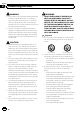
Section Connecting the units CAUTION En F O ACC position STAR 2 Important ! This unit cannot be installed in a vehicle without ACC (accessory) position on the ignition switch. N ! PIONEER does not recommend that you install or service your display unit yourself. Installing or servicing the product may expose you to risk of electric shock or other hazards. Refer all installation and servicing of your display unit to authorized Pioneer service personnel.
Section Connecting the units 01 English — Never cut the insulation of the power cable of this unit in order to share the power with other devices. The current capacity of the cable is limited. — Use a fuse of the rating prescribed. — Never wire the negative speaker cable directly to ground. — Never band together negative cables of multiple speakers. ! When this unit is on, control signals are sent through the blue/white cable.
Section 01 Connecting the units Connecting the power cord Navigation system (AVIC-F220 (sold separately)). 26 pin cable (Supplied with Navigation system) Please contact your dealer to inquire about the connectable navigation system. RGB input Note: Depending on the kind of vehicle, the function of 2* and 4* may be different. In this case, be sure to connect 1* to 4* and 3* to 2*. Antenna input 2* 1* 4* 3* This product Insert the 26 pin cable in the direction indicated in the figure.
Section Connecting the units 01 English Wired remote input Hard-wired remote control adaptor can be connected (sold separately). Fuse resistor Violet/white Of the two lead wires connected to the back lamp, connect the one in which the voltage changes when the gear shift is in the REVERSE (R) position. This connection enables the unit to sense whether the car is moving forwards or backwards. Yellow/black If you use an equipment with Mute function, wire this lead to the Audio Mute lead on that equipment.
Section 01 Connecting the units When connecting to separately sold power amp Rear output or subwoofer output Power amp (sold separately) To rear output or subwoofer output Power amp (sold separately) To front output Front output This product Connect with RCA cables (sold separately) Blue/white Connect to system control terminal of the power amp (max. 300 mA 12 V DC).
Section Connecting the units 01 Display with RCA input jacks (sold separately) English When connecting the external video component and the display To video input Video input (V IN) Rear monitor output (V OUT) RCA cables (sold separately) To video output To audio outputs This product Audio inputs (L IN, R IN) External video component (sold separately) ! It is necessary to change AV Input in System Menu when connecting the external video component.
Section 01 Connecting the units When connecting with a rear view camera Rear view camera input (R.C IN) When this product is used with a rear view camera, it is possible to automatically switch from the video to rear view image when the gear shift is moved to REVERSE (R). WARNING USE INPUT ONLY FOR REVERSE OR MIRROR IMAGE REAR VIEW CAMERA. OTHER USE MAY RESULT IN INJURY OR DAMAGE. This product RCA cable (sold separately) To video output Fuse resistor CAUTION ! The screen image may appear reversed.
Section Installation English Notes ! Check all connections and systems before final installation. ! Do not use unauthorized parts as this may cause malfunctions. ! Consult your dealer if installation requires drilling of holes or other modifications to the vehicle. ! Do not install this unit where: — it may interfere with operation of the vehicle. — it may cause injury to a passenger as a result of a sudden stop.
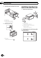
Section Installation 02 2 Install this unit and fasten the screws. Installation using the screw holes on the side of the unit 1 Remove the side brackets. 1 1 2 2 1 Dashboard 2 Screw (3 mm × 6 mm) (Supplied with this unit) 3 Attach the trim ring. 1 Side bracket (Supplied with this unit) 2 Screw for fixing the side bracket (5 mm × 9 mm) (Supplied with this unit) 2 Fastening the unit to the factory radiomounting bracket.
Section Installation 02 English 1 2 3 4 1 2 3 4 If the pawl gets in the way, bend it down. Factory radio mounting bracket Tapping screw (5 mm × 8 mm) Dashboard or console Note In some types of vehicles, discrepancy may occur between the unit and the dashboard. If this happens, use the supplied frame to fill the gap.
Section 01 Connexion des appareils ATTENTION ! Pour éviter le risque d’accident et une violation potentielle des lois applicables, l’écran du siège avant ne doit en aucun cas être regardé pendant la conduite du véhicule. En outre, les écrans arrière ne doivent pas être placés dans un endroit où ils constituent visiblement une distraction pour le conducteur.
Section Connexion des appareils provoquer un incendie ou un dysfonctionnement. Français — Placez les câbles à l’écart de toutes les parties mobiles, telles que le levier de vitesse et les rails des sièges. — Placez les câbles à l’écart de tous les endroits chauds, par exemple les sorties de chauffage. — Ne reliez pas le câble jaune à la batterie à travers le trou dans le compartiment moteur. — Recouvrez tous les connecteurs de câbles qui ne sont pas connectés avec du ruban adhésif isolant.
Section 01 Connexion des appareils Connexion du cordon d’alimentation 14 Fr
Section Connexion des appareils 01 Français Fr 15
Section 01 Connexion des appareils Lors de la connexion à un amplificateur de puissance vendu séparément 16 Fr
Section Connexion des appareils 01 Lors de la connexion du composant vidéo externe et de l’écran Français ! Il est nécessaire de remplacer AV Input par System Menu lors de la connexion du composant vidéo externe. Lors de l’utilisation d’un écran connecté à la sortie vidéo arrière La sortie vidéo arrière de cet appareil est prévue pour connecter un écran afin de permettre aux passagers des sièges arrières de regarder des DVD, etc.
Section 01 Connexion des appareils Lors de la connexion à une caméra de vue arrière Lorsque cet appareil est utilisé avec une caméra de vue arrière, il est possible de basculer automatiquement la vidéo sur l’image de la caméra de vue arrière lorsque le levier de vitesse est mis en position MARCHE ARRIÈRE (R). ATTENTION UTILISEZ CETTE ENTRÉE SEULEMENT POUR UNE CAMÉRA DE VUE ARRIÈRE DONNANT UNE IMAGE INVERSÉE OU MIROIR. TOUTE AUTRE UTILISATION PEUT PROVOQUER DES BLESSURES OU DES DOMMAGES.
Section Installation 1 Français Remarques ! Vérifiez toutes les connexions et tous les systèmes avant l’installation finale. ! N’utilisez pas de pièces non autorisées car il peut en résulter des dysfonctionnements. ! Consultez votre revendeur si l’installation nécessite le perçage de trous ou d’autres modifications du véhicule. ! N’installez pas cet appareil là où : — il peut interférer avec l’utilisation du véhicule. — il peut blesser un passager en cas d’arrêt soudain du véhicule.
Section Installation 02 2 Installez l’appareil et serrez les vis. Installation à l’aide des trous de vis sur les côtés de l’appareil 1 Retirez les fixations latérales. 1 1 2 2 1 Tableau de bord 2 Vis (3 mm × 6 mm) (fourni avec cet appareil) 3 Fixez l’anneau de garniture. 1 Fixation latérale (fourni avec cet appareil) 2 Vis pour fixation latérale (5 × 9 mm) (fourni avec cet appareil) 2 Fixation de l’appareil sur le support de montage radio d’usine.
Section Installation 02 1 2 Français 3 4 1 Courbez la languette vers le bas si elle gêne. 2 Support de montage radio d’usine 3 Vis taraudeuse (5 mm × 8 mm) 4 Tableau de bord ou console Remarque Dans certains véhicules, il peut y avoir un écart entre l’appareil et tableau de bord. Dans ce cas, utilisez le cadre fourni pour combler l’espace.
Sezione Collegamento delle unità ! Per evitare il rischio di incidenti e la potenziale violazione della normativa applicabile, la visione dei video dal sedile anteriore è vietata mentre il veicolo è in movimento. Inoltre, i display posteriori non devono trovarsi in posizioni che possano distrarre visivamente il conducente. ! In alcuni Stati o Paesi la visione di immagini su un display installato all’interno di un veicolo, anche da parte di persone diverse dal conducente, potrebbe essere illegale.
Sezione Collegamento delle unità ne, quali amplificatori di potenza) devono essere collegati separatamente. In caso contrario, se scollegati accidentalmente, potrebbero provocare incendi o malfunzionamenti. Italiano — Assicurare i cavi con morsetti per cavi o nastro adesivo. Per proteggere i cavi, avvolgere nastro adesivo attorno agli stessi nei punti in cui entrano in contatto con parti metalliche.
Sezione 01 Collegamento delle unità Collegamento del cavo di alimentazione 24 It
Sezione Collegamento delle unità 01 Italiano It 25
Sezione 01 Collegamento delle unità Collegamento a un amplificatore di potenza venduto separatamente 26 It
Sezione Collegamento delle unità 01 Collegamento di un componente video esterno e del display Italiano ! È necessario cambiare AV Input in System Menu quando si collega componente video esterno. Utilizzo di un display collegato all’uscita video posteriore L’uscita video posteriore di questo prodotto è destinata al collegamento di un display che consente ai passeggeri dei sedili posteriori la visione dei DVD, ecc.
Sezione 01 Collegamento delle unità Collegamento a una telecamera per retromarcia Se questo prodotto viene utilizzato con una telecamera per retromarcia, è possibile passare automaticamente dall’immagine video all’immagine della telecamera per retromarcia quando viene inserita la RETROMARCIA (R). AVVERTENZA UTILIZZARE IL SEGNALE IN INGRESSO ESCLUSIVAMENTE PER IMMAGINI INVERTITE O SPECULARI TRASMESSE DALLA TELECAMERA PER RETROMARCIA. USI DIVERSI POTREBBERO PROVOCARE LESIONI O DANNI.
Sezione Installazione 1 2 1 Supporto (Fornito con l’unità) 2 Vite (3 mm × 6 mm) (Fornito con l’unità) Italiano Note ! Controllare tutti i collegamenti e i sistemi prima dell’installazione finale. ! Non utilizzare componenti non approvati, poiché potrebbero provocare malfunzionamenti. ! Consultare il rivenditore se l’installazione richiede la trapanatura di fori o altre modifiche del veicolo. ! Non installare questa unità se: — potrebbe interferire con il funzionamento del veicolo.
Sezione Installazione 02 2 Installare l’unità e avvitare le viti. Installazione utilizzando i fori delle viti ai lati dell’unità 1 Rimuovere le staffe laterali. 1 1 2 2 1 Cruscotto 2 Vite (3 mm × 6 mm) (Fornito con l’unità) 3 Collocare la guarnizione. 1 Staffa laterale (Fornito con l’unità) 2 Vite per fissare la staffa laterale (5 × 9 mm) (Fornito con l’unità) 2 Fissare l’unità alla staffa di montaggio radio.
Sezione Installazione 02 1 2 3 Italiano 4 1 Quando la linguetta si inserisce nel foro, piegarla verso il basso. 2 Staffa di montaggio radio 3 Vite autofilettante (5 mm × 8 mm) 4 Cruscotto o console Nota In alcuni tipi di veicoli, è possibile che potrebbe crearsi un dislivello tra l’unità e il cruscotto. In questo caso, utilizzare la cornice fornita con il prodotto per riempire lo spazio.
Sección Conexión de las unidades ! Para evitar el riesgo de accidentes y la posible violación de las leyes pertinentes, nunca se debe visualizar el vídeo de los asientos delanteros mientras se maneja el vehículo. Además, las pantallas traseras no deben estar en un lugar donde representen una distracción visual para el conductor. ! En algunos países o estados, puede ser ilícita la visualización de imágenes en un display dentro de un vehículo, incluso por otras personas que no sean el conductor.
Sección Conexión de las unidades 01 Español — Coloque todos los cables alejados de lugares calientes, como cerca de la salida del calefactor. — No conecte el cable amarillo a la batería pasándolo a través del orificio hasta el compartimiento del motor. — Cubra con cinta aislante los conectores de cables que queden desconectados. — No acorte ningún cable. — Nunca corte el aislamiento del cable de alimentación de esta unidad para compartir la corriente con otros equipos.
Sección 01 Conexión de las unidades Conexión del cable de alimentación 34 Es
Sección Conexión de las unidades 01 Español Es 35
Sección 01 Conexión de las unidades Conexión a un amplificador de potencia comprado por separado 36 Es
Sección Conexión de las unidades 01 Conexión con el componente de vídeo externo y el display Español ! Es necesario cambiar AV Input en System Menu al conectar el componente de vídeo externo. Uso de un display conectado a la salida posterior de vídeo La salida de vídeo posterior de este producto sirve para conectar un display que permita a los pasajeros de los asientos traseros ver un DVD, etc. ADVERTENCIA ! Nunca instale el display en un lugar visible para el conductor.
Sección 01 Conexión de las unidades Conexión con una cámara retrovisora Cuando este producto se usa con una cámara retrovisora, es posible que cambie automáticamente a la imagen de la vista trasera cuando se mueve la palanca de cambio a MARCHA ATRÁS (R). ADVERTENCIA UTILICE LA ENTRADA SÓLO PARA LA MARCHA ATRÁS O CON LA IMAGEN DE ESPEJO DE LA CÁMARA RETROVISORA. OTROS USOS PODRÍAN PROVOCAR HERIDAS O DAÑOS. PRECAUCIÓN ! La imagen de la pantalla puede aparecer invertida.
Sección Instalación 1 2 1 Soporte (suministrado con esta unidad) 2 Tornillo (3 mm × 6 mm) (suministrado con esta unidad) Instalación con el soporte y la carcasa lateral 1 Instale el soporte en el panel. Después de insertar el soporte en el panel, seleccione las pestañas que se acoplen al espesor del material del panel, y dóblelas (instale esta unidad tan firmemente como sea posible, usando las pestañas superior e inferior; para fijar la unidad, doble las pestañas 90 grados).
Sección Instalación 02 2 Instale esta unidad y apriete los tornillos. Instalación usando los agujeros para tornillos ubicados en ambos costados de la unidad 1 Retire las carcasas laterales. 1 1 2 1 Salpicadero 2 Tornillo (3 mm × 6 mm) (suministrado con esta unidad) 3 2 Coloque el anillo de guarnición. 1 Carcasa lateral (suministrado con esta unidad) 2 Tornillo para ajustar la carcasa lateral (5 × 9 mm) (suministrado con esta unidad) 2 Fijar la unidad al soporte de montaje de radio de fábrica.
Sección Instalación 02 1 2 3 4 1 Si la lengüeta supone un impedimento, dóblela hacia abajo. 2 Soporte de montaje de radio de fábrica 3 Tornillo con rosca cortante (5 mm × 8 mm) 4 Salpicadero o consola Español Nota Es posible que la unidad y el panel no encajen perfectamente en algunos vehículos. Si esto ocurre, utilice el marco suministrado para tapar el hueco.
Abschnitt Anschließen der Geräte ! Um Unfallrisiken und Verstöße gegen geltende Gesetze zu vermeiden, darf während der Fahrt auf den vorderen Sitzen kein Video betrachtet werden. Darüber hinaus sollten Heckdisplays niemals in einer Position angebracht werden, in der sie den Fahrer visuell ablenken. ! In einigen Ländern oder Regionen kann die Anzeige von Bildern auf einem Display im Fahrzeug selbst für Bei- und Mitfahrer verboten sein. Wenn derartige Vorschriften vorliegen, müssen sie beachtet werden, d.
Abschnitt Anschließen der Geräte ! Verbinden Sie das blau/weiße Kabel niemals mit der Leistungsklemme des externen Leistungsverstärkers. Darüber hinaus darf das Kabel keinesfalls mit der Leistungsklemme der Fahrzeugantenne verbunden werden. Andernfalls kann es zu einer Entleerung oder Funktionsstörung der Fahrzeugbatterie kommen. ! Das schwarze Kabel gewährleistet die Erdung.
Abschnitt 01 Anschließen der Geräte Anschluss des Stromkabels 44 De
Abschnitt Anschließen der Geräte 01 Deutsch De 45
Abschnitt 01 Anschließen der Geräte Bei Anschluss an einen separat erhältlichen Leistungsverstärker 46 De
Abschnitt Anschließen der Geräte 01 Bei Anschluss der externen Videokomponente mit dem Display Deutsch ! Beim Anschließen der externen Videokomponente ist es notwendig, unter System Menu die Option AV Input zu ändern. Bei Verwendung eines mit dem Videoheckausgang angeschlossenen Displays Der Videoheckausgang dieses Geräts ermöglicht den Anschluss eines Displays, auf dem für die Mitfahrer auf dem Rücksitz DVDs etc. abgespielt werden können.
Abschnitt 01 Anschließen der Geräte Bei Anschluss mit einer Heckbildkamera Wird dieses Produkt zusammen mit einer Heckbildkamera verwendet, ist es möglich, beim Einlegen des Rückwärtsgang (REVERSE) automatisch zum Videobild der Heckbildkamera zu wechseln. WARNUNG VERWENDEN SIE DEN EINGANG NUR FÜR EINE SPIEGELVERKEHRTE ODER SPIEGELBILD-HECKBILDKAMERA. EINE ANDERE VERWENDUNG KÖNNTE VERLETZUNGEN ODER SACHSCHÄDEN ZUR FOLGE HABEN. VORSICHT ! Das Bild kann ggf. spiegelverkehrt wiedergegeben werden.
Abschnitt Installation 1 2 1 Halterung (mit dieser Einheit mitgeliefert) 2 Schraube (3 × 6 mm) (mit dieser Einheit mitgeliefert) Installation mit der Halterung und Seitenklammern 1 Bringen Sie die Halterung am Armaturenbrett an. Wählen und biegen Sie nach dem Einsetzen der Halterung im Armaturenbrett die Klammern entsprechend der Dicke des Armaturenbrettmaterials. (Setzen Sie diese Einheit so fest wie möglich mithilfe der oberen und unteren Klammern ein.
Abschnitt Installation 02 2 Setzen Sie die Einheit ein und ziehen Sie die Schrauben fest. Bei Anbringen mithilfe der Schraubenlöcher auf beiden Seiten der Einheit 1 Entfernen Sie die Seitenklammern. 1 1 2 2 1 Armaturenbrett 2 Schraube (3 × 6 mm) (mit dieser Einheit mitgeliefert) 3 Setzen Sie den Einpassungsring ein.
Abschnitt Installation 02 1 2 3 4 1 Sollte die Sperrklinke im Weg sein, biegen Sie sie nach unten. 2 Werkseitig bereitgestellte Radio-Montageklammer 3 Blechschraube (5 × 8 mm) 4 Armaturenbrett oder Konsole Hinweis Bei manchen Fahrzeugtypen kann es eine Lücke zwischen der Einheit und dem Armaturenbrett geben. Verwenden Sie in diesem Fall den mitgelieferten Rahmen zur Überbrückung des Abstands.
Hoofdstuk De toestellen aansluiten ! Om ongevallen en mogelijke wetsovertreding te voorkomen, mag de video-functie voorin nooit worden gebruikt terwijl het voertuig wordt bestuurd. De displays achterin mogen niet worden gemonteerd op een plaats waar de bestuurder ze kan zien of erdoor kan worden afgeleid. ! In sommige landen of staten is het verbod op kijken naar beelden op een display in een voertuig niet beperkt tot de bestuurder.
Hoofdstuk De toestellen aansluiten 01 Nederlands — Leg kabels niet op plaatsen die heet kunnen worden, zoals dicht bij de kachel. — Sluit de gele kabel niet op de accu aan via een gat in het motorcompartiment. — Dek alle ongebruikte kabelaansluitingen af met isolatietape. — Maak de kabels niet korter. — Verwijder nooit de isolatie van de voedingskabel van dit toestel om andere apparaten van stroom te voorzien. De stroomcapaciteit van de voedingskabel is beperkt.
Hoofdstuk 01 De toestellen aansluiten De elektriciteitskabel aansluiten 54 Nl
Hoofdstuk De toestellen aansluiten 01 Nederlands Nl 55
Hoofdstuk 01 De toestellen aansluiten Aansluiten op een los verkrijgbare versterker 56 Nl
Hoofdstuk De toestellen aansluiten 01 Het externe videoapparaat op het scherm aansluiten ! Wanneer u het externe videoapparaat aansluit moet u AV Input wijzigen in System Menu. Nederlands Een scherm aansluiten op de video-uitgang aan de achterzijde De achteruitgang van dit toestel is geschikt voor aansluiting van een display zodat passagiers op de achterbank naar een dvd kunnen kijken.
Hoofdstuk 01 De toestellen aansluiten Aansluiten op een achteruitrijcamera Als u dit product in combinatie met een achteruitrijcamera gebruikt, kunt u het beeld automatisch laten schakelen naar weergave van de achteruitrijcamera wanneer u de versnellingspook in de stand ACHTERUIT (R) zet. WAARSCHUWING GEBRUIK DEZE INGANG ALLEEN VOOR EEN ACHTERUITRIJCAMERA DIE HET BEELD OMGEKEERD OF IN SPIEGELBEELD WEERGEEFT. ANDER GEBRUIK KAN RESULTEREN IN VERWONDINGEN OF SCHADE.
Hoofdstuk Installatie Opmerkingen ! Controleer alle aansluitingen en systemen voordat u de installatie voltooit. ! Gebruik geen onderdelen van andere fabrikanten; deze kunnen storingen veroorzaken. ! Neem contact op met uw dealer als er voor de installatie gaten moeten worden geboord of als er andere aanpassingen aan het voertuig nodig zijn. ! Installeer dit toestel niet op een plaats waar: — het de besturing van het voertuig kan belemmeren. — het de inzittenden kan verwonden bij een noodstop.
Hoofdstuk Installatie 02 2 Monteer het toestel en schroef de schroeven vast. Monteren met de schroefgaten aan de zijkant van het toestel 1 Verwijder de zijklemmen. 1 1 2 2 1 Dashboard 2 Schroef (3 mm × 6 mm) (Wordt met dit toestel meegeleverd) 3 Bevestig de sierlijst. 1 Zijklem (Wordt met dit toestel meegeleverd) 2 Schroef voor het bevestigen van de zijklem (5 x 9 mm) (Wordt met dit toestel meegeleverd) 2 Bevestig het toestel aan de radiomonteerklem.
Hoofdstuk Installatie 02 1 2 3 4 1 Als het uitsteekseltje in de weg zit, buigt u het omlaag. 2 Radiomonteerklem 3 Zelftappende schroef (5 mm × 8 mm) 4 Dashboard of console Opmerking In sommige voertuigen kan er een discrepantie ontstaan tussen het toestel en het dashboard. Als dit het geval is, gebruikt u het meegeleverde montuur om het gat te vullen.
Nl
Nederlands 63 Nl
PIONEER CORPORATION 1-1, Shin-ogura, Saiwai-ku, Kawasaki-shi, Kanagawa 212-0031, JAPAN PIONEER ELECTRONICS (USA) INC. P.O. Box 1540, Long Beach, California 90801-1540, U.S.A. TEL: (800) 421-1404 PIONEER EUROPE NV Haven 1087, Keetberglaan 1, B-9120 Melsele, Belgium/Belgique TEL: (0) 3/570.05.11 PIONEER ELECTRONICS ASIACENTRE PTE. LTD. 253 Alexandra Road, #04-01, Singapore 159936 TEL: 65-6472-7555 PIONEER ELECTRONICS AUSTRALIA PTY. LTD.