English Français DVD RDS AV RECEIVER AUTORADIO AV RDS LECTEUR DE DVD SINTOLETTORE DVD RDS CON AV RADIO AV RDS CON DVD DVD-RDS-AV-EMPFÄNGER DVD RDS AV-ONTVANGER Deutsch Nederlands <1> Español Installation Manual Manuel d’installation Manuale d’installazione Manual de instalación Installationsanleitung Installatiehandleiding Italiano AVH-4400BT AVH-3400DVD AVH-2400BT AVH-1400DVD
Section Connecting the units CAUTION En F O ACC position STAR 2 Important ! This unit cannot be installed in a vehicle without ACC (accessory) position on the ignition switch. N ! PIONEER does not recommend that you install or service your display unit yourself. Installing or servicing the product may expose you to risk of electric shock or other hazards. Refer all installation and servicing of your display unit to authorized Pioneer service personnel.
Section Connecting the units 01 English — Never cut the insulation of the power cable of this unit in order to share the power with other devices. The current capacity of the cable is limited. — Use a fuse of the rating prescribed. — Never wire the negative speaker cable directly to ground. — Never band together negative cables of multiple speakers. ! When this unit is on, control signals are sent through the blue/white cable.
Section 01 Connecting the units Connecting the power cord Navigation system (AVIC-F220 (sold separately)) 4m 26 pin cable (Supplied with navigation unit) Please contact your dealer to inquire about the connectable navigation unit. Insert the 26 pin cable in the direction indicated in the figure. Fuse (10 A) Note: Depending on the kind of vehicle, the function of 2* and 4* may be different. In this case, be sure to connect 1* to 4* and 3* to 2*.
Section Connecting the units 01 English Microphone (AVH-4400BT/AVH-2400BT only) Microphone input (AVH-4400BT/AVH-2400BT only) Wired remote input Hard-wired remote control adaptor can be connected (sold separately). Violet/white Of the two lead wires connected to the back lamp, connect the one in which the voltage changes when the gear shift is in the REVERSE (R) position. This connection enables the unit to sense whether the car is moving forwards or backwards.
Section 01 Connecting the units When connecting to separately sold power amp Rear output Front output This product Power amp (sold separately) To rear output Power amp (sold separately) To front output Power amp (sold separately) Subwoofer output To subwoofer output Connect with RCA cables (sold separately) Blue/white Connect to system control terminal of the power amp (max. 300 mA 12 V DC). System remote control Blue/white (5*) Blue/white (6*) Connect to auto-antenna relay control terminal (max.
Section Connecting the units 01 English When connecting with optional CD-IU201V cable This product iPod with video capabilities (sold separately) USB input Dock connector 1.5 m AUX input (AUX) USB cable (Supplied with this unit for AVH-4400BT/AVH-3400DVD.
Section 01 Connecting the units When connecting the external video component and the display External video component (sold separately) To audio outputs To video output Audio inputs (L IN, R IN) RCA cables (sold separately) Video input (V IN) This product Rear monitor output (V OUT) To video input Display with RCA input jacks (sold separately) ! It is necessary to change AV Input in System Menu when connecting the external video component.
Section Connecting the units When the shift lever is switched to REVERSE (R), the display on this unit automatically switches to the rear view image. You need to set the Camera Polarity properly in the system menu. You can also switch the rear view image by pressing the touch key. For details, refer to operation manual. WARNING USE INPUT ONLY FOR REVERSE OR MIRROR IMAGE REAR VIEW CAMERA. OTHER USE MAY RESULT IN INJURY OR DAMAGE. CAUTION ! You must use a camera which outputs mirror reversed images.
Section 02 Installation Notes ! Check all connections and systems before final installation. ! Do not use unauthorized parts as this may cause malfunctions. ! Consult your dealer if installation requires drilling of holes or other modifications to the vehicle. ! Do not install this unit where: — it may interfere with operation of the vehicle. — it may cause injury to a passenger as a result of a sudden stop.
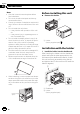
Section Installation English 2 02 1 Install this unit. 2 1 3 1 Dashboard Installation using the screw holes on the side of the unit % Fastening the unit to the factory radiomounting bracket. Position the unit so that its screw holes are aligned with the screw holes of the bracket, and tighten the screws at 3 locations on each side. 4 1 2 3 4 If the pawl gets in the way, bend it down.
Section Installation 02 ! Releasing the front panel allows easier access to the trim ring. 2 Insert the supplied extraction keys into both sides of the unit until they click into place. 3 Pull the unit out of the dashboard. Installing the microphone (AVH-4400BT/AVH-2400BT only) CAUTION It is extremely dangerous to allow the microphone lead to become wound around the steering column or shift lever. Be sure to install the unit in such a way that it will not obstruct driving.
Section Installation 02 2 Install the microphone clip on the rear side of the steering column. 1 English 1 2 1 Microphone clip 2 Clamp Use separately sold clamps to secure the lead where necessary inside the vehicle. 2 When installing the microphone on the steering column 1 Install the microphone on the microphone clip. 1 2 1 Double-sided tape 2 Clamp Use separately sold clamps to secure the lead where necessary inside the vehicle.
Section 01 Connexion des appareils ATTENTION ! Pour éviter le risque d’accident et une violation potentielle des lois applicables, l’écran du siège avant ne doit en aucun cas être regardé pendant la conduite du véhicule. En outre, les écrans arrière ne doivent pas être placés dans un endroit où ils constituent visiblement une distraction pour le conducteur.
Section Connexion des appareils 01 Français — Placez les câbles à l’écart de tous les endroits chauds, par exemple les sorties de chauffage. — Ne reliez pas le câble jaune à la batterie à travers le trou dans le compartiment moteur. — Recouvrez tous les connecteurs de câbles qui ne sont pas connectés avec du ruban adhésif isolant. — Ne raccourcissez pas les câbles. — Ne coupez jamais l’isolation du câble d’alimentation de cet appareil pour partager l’alimentation avec d’autres appareils.
Section 01 Connexion des appareils Connexion du cordon d’alimentation Unité de navigation (AVIC-F220 (vendue séparément)). Câble 26 broches (fourni avec l’unité de navigation) Veuillez contacter votre revendeur pour en savoir plus sur les unités de navigation pouvant être raccordées. Remarque: En fonction du type de véhicule, la fonction de 2* et de 4* peut différer. Sans ce cas, assurez-vous de connecter 1* à 4* et 3* à 2*. 4m Insérez le câble 26 broches dans la direction indiquée sur la figure.
Section Connexion des appareils 01 Microphone (AVH-4400BT/AVH-2400BT seulement) Entrée microphone (AVH-4400BT/AVH-2400BT seulement) Français Entrée pour télécommande câblée Un adaptateur de télécommande câblée peut être connecté à cette prise (vendu séparément). Violet/blanc Des deux conducteurs connectés au feu de recul, connectez celui pour lequel la tension change quand le sélecteur de vitesse est sur la position REVERSE (R).
Section 01 Connexion des appareils Lors de la connexion à un amplificateur de puissance vendu séparément Sortie arrière Sortie avant Cet appareil Amplificateur de puissance (vendu séparément) À la sortie arrière Amplificateur de puissance (vendu séparément) À la sortie avant Sortie du caisson de grave Amplificateur de puissance (vendu séparément) À la sortie du caisson de grave Connectez aux câbles cinch (RCA) (vendus séparément) Bleu/blanc Connectez à la prise de commande du système de l’amplific
Section Connexion des appareils 01 Lors de la connexion avec le câble CD-IU201V en option Cet appareil iPod avec capacité vidéo (vendu séparément) Entrée USB Connecteur Dock Français 1,5 m Entrée AUX (AUX) Câble USB (Fourni avec cet appareil dans le cas de l’AVH-4400BT/ AVH-3400VDVD. Vendu séparément 2m pour les autres modèles.
Section 01 Connexion des appareils Lors de la connexion du composant vidéo externe et de l’écran Appareil vidéo externe (vendu séparément) Aux sorties audio À la sortie vidéot Entrée audio (L IN, R IN) Entrée vidéo (V IN) Câbles à fiches Cinch (RCA) (vendu séparément) Cet appareil Sortie du moniteur arrière (V OUT) Vers l’entrée vidéo Écran muni de prises d’entrée Cinch (RCA) (vendu séparément) ! Il est nécessaire de remplacer AV Input par System Menu lors de la connexion du composant vidéo exter
Section Connexion des appareils Lors de la connexion à une caméra de vue arrière Entrée de la caméra de recul (R.C IN) Cet appareil Français Quand le levier de vitesse est en position MARCHE ARRIÈRE (R), l’affichage bascule automatiquement sur l’image de vue arrière. Vous devez régler Camera Polarity correctement dans le menu système. Vous pouvez également basculer sur l’image de vue arrière en appuyant sur la touche tactile. Pour plus de détails, reportez-vous au mode d’emploi.
Section 02 Installation Remarques ! Vérifiez toutes les connexions et tous les systèmes avant l’installation finale. ! N’utilisez pas de pièces non autorisées car il peut en résulter des dysfonctionnements. ! Consultez votre revendeur si l’installation nécessite le perçage de trous ou d’autres modifications du véhicule. ! N’installez pas cet appareil là où : — il peut interférer avec l’utilisation du véhicule. — il peut blesser un passager en cas d’arrêt soudain du véhicule.
Section Installation Installation avec le support Installation à l’aide des trous de vis sur les côtés de l’appareil % Fixation de l’appareil sur le support de montage radio d’usine. Positionnez l’appareil de sorte que les trous des vis soient alignés avec les trous des vis sur le support, puis serrez les vis aux 3 emplacements de chaque côté de l’appareil. Français 1 Installez le support dans le tableau de bord.
Section Installation 02 Remarque Dans certains véhicules, il peut y avoir un écart entre l’appareil et tableau de bord. Dans ce cas, utilisez le cadre fourni pour combler l’espace. Installation du microphone (AVH-4400BT/AVH-2400BT uniquement) Retrait de l’appareil Il est extrêmement dangereux de laisser le fil du microphone s’enrouler autour de la colonne de direction ou du levier de vitesse. Assurez-vous d’installer cet appareil de telle manière qu’il ne gêne pas la conduite.
Section Installation 02 1 2 Installez le clip microphone sur la face arrière de la colonne de direction. 1 Français 2 1 Clip microphone 2 Serre-fils Utilisez des serre-fils vendus séparément pour fixer le fil là où c’est nécessaire dans le véhicule. 2 Si vous installez le microphone sur la colonne de direction 1 Installez le microphone sur le clip microphone. 1 2 1 Bande double face 2 Serre-fils Utilisez des serre-fils vendus séparément pour fixer le fil là où c’est nécessaire dans le véhicule.
Sezione Collegamento delle unità ! Per evitare il rischio di incidenti e la potenziale violazione della normativa applicabile, la visione dei video dal sedile anteriore è vietata mentre il veicolo è in movimento. Inoltre, i display posteriori non devono trovarsi in posizioni che possano distrarre visivamente il conducente. ! In alcuni Stati o Paesi la visione di immagini su un display installato all’interno di un veicolo, anche da parte di persone diverse dal conducente, potrebbe essere illegale.
Sezione Collegamento delle unità sione, quali l’amplificatore di potenza) devono essere collegati separatamente. In caso contrario, se scollegati accidentalmente, potrebbero provocare incendi o malfunzionamenti. Italiano — Assicurare i cavi con morsetti per cavi o nastro adesivo. Per proteggere i cavi, avvolgere nastro adesivo attorno agli stessi nei punti in cui entrano in contatto con parti metalliche.
Sezione 01 Collegamento delle unità Collegamento del cavo di alimentazione Unità di navigazione (AVIC-F220 (in vendita a parte)). Cavo con spine da 26 contatti (in dotazione all’unità di navigazione) Per informazioni sugli apparecchi di navigazione collegabili si prega di rivolgersi al proprio rivenditore. Nota: In funzione del tipo di veicolo le funzione di 2* e di 4* potrebbe differire. In tal caso collegare 1* a 4* e 3* a 2*.
Sezione Collegamento delle unità 01 Microfono (solo AVH-4400BT/AVH-2400BT) Ingresso microfono (solo AVH-4400BT/AVH-2400BT) Ingresso per telecomando a filo Qui si collega mediante cavo l’adattatore per telecomando (venduto a parte). Italiano Violetto/bianco Dei due fili isolati collegati alla spia posteriore, collegare quello nel quale cambia il voltaggio quando la leva del cambio è in posizione di REVERSE (R).
Sezione 01 Collegamento delle unità Quando l’unità viene collegata a un amplificatore di potenza venduto a parte Uscita posteriore Uscita anteriore Questo apparecchio Amplificatore di potenza (venduto a parte) All’uscita posteriore Amplificatore di potenza (venduto a parte) All’uscita anteriore Uscita per subwoofer Amplificatore di potenza (venduto a parte) All’uscita per subwoofer Da collegare ai cavi RCA (venduti a parte) Blu/bianco Da collegare al terminale di controllo di sistema dell’amplific
Sezione Collegamento delle unità 01 Collegamento con il cavo opzionale CD-IU201V Questo apparecchio iPod con capacità video (acquistabile separatamente) Ingresso USB Connettore Dock 1,5 m Ingresso AUX (AUX) Cavo USB (Fornito con questo apparecchio per il collegamento dell’AVH-4400BT o dell’AVH-3400DVD. In vendita a parte per altri modelli.
Sezione 01 Collegamento delle unità Collegamento di un componente video esterno e del display Componente video esterno (venduto a parte) Alle uscite audio All’uscita video Ingresso audio (L IN, R IN) Ingresso video (V IN) Questo apparecchio Uscita per monitor posteriore (V OUT) Cavi RCA (venduti separatamente) All’ingresso video Schermo con prese di ingresso di tipo RCA (venduto a parte) ! È necessario cambiare AV Input in System Menu quando si collega un componente video esterno.
Sezione Collegamento delle unità Collegamento a una telecamera per retromarcia Quando viene inserita la RETROMARCIA (R), il display passa automaticamente all’immagine della telecamera per retromarcia. È necessario impostare Camera Polarity correttamente nel menu di sistema. È inoltre possibile cambiare l’immagine della telecamera per retromarcia toccando il tasto sul touch panel. Per ulteriori dettagli, vedere il manuale d’istruzioni. 01 Ingresso alla videocamera di retromarcia (R.
Sezione 02 Installazione Note ! Controllare tutti i collegamenti e i sistemi prima dell’installazione finale. ! Non utilizzare componenti non approvati, poiché potrebbero provocare malfunzionamenti. ! Consultare il rivenditore se l’installazione richiede la trapanatura di fori o altre modifiche del veicolo. ! Non installare questa unità se: — potrebbe interferire con il funzionamento del veicolo. — potrebbe procurare lesioni al passeggero in caso di arresto improvviso del veicolo.
Sezione Installazione 02 Installazione utilizzando il supporto Installazione utilizzando i fori delle viti ai lati dell’unità 1 Installare il supporto nel cruscotto. Dopo aver inserito il supporto nel cruscotto, scegliere e piegare le linguette in modo che corrispondano allo spessore del materiale del cruscotto. (Installare l’unità utilizzando le linguette superiori e inferiori in modo che sia fissata il più saldamente possibile. Per un montaggio sicuro, piegare le linguette a 90 gradi).
Sezione Installazione 02 Nota In alcuni tipi di veicoli, potrebbe crearsi un dislivello tra l’unità e il cruscotto. In questo caso, utilizzare la cornice fornita con il prodotto per riempire lo spazio. Rimozione dell’unità 1 Rimuovere la guarnizione. Installazione del microfono (solo modelli AVH-4400BT/ AVH-2400BT) ATTENZIONE È estremamente pericoloso se il filo di sostegno del microfono si avvolge attorno al piantone dello sterzo o alla leva del cambio.
Sezione Installazione 02 1 2 Installare la clip del microfono sul lato posteriore del piantone dello sterzo. 1 2 Italiano 1 Clip del microfono 2 Morsetto Utilizzare i morsetti venduti separatamente per assicurare il cavo, ove necessario, all’interno del veicolo. 2 Installazione del microfono sul piantone dello sterzo 1 Installare il microfono sulla clip del microfono.
Sección Conexión de las unidades ! Para evitar el riesgo de accidentes y la posible violación de las leyes pertinentes, nunca se debe visualizar el vídeo de los asientos delanteros mientras se maneja el vehículo. Además, las pantallas traseras no deben estar en un lugar donde representen una distracción visual para el conductor. ! En algunos países o estados, puede ser ilícita la visualización de imágenes en un display dentro de un vehículo, incluso por otras personas que no sean el conductor.
Sección Conexión de las unidades 01 Español — Coloque todos los cables alejados de lugares calientes, como cerca de la salida del calefactor. — No conecte el cable amarillo a la batería pasándolo a través del orificio hasta el compartimento del motor. — Cubra con cinta aislante los conectores de cables que queden desconectados. — No acorte ningún cable. — Nunca corte el aislamiento del cable de alimentación de esta unidad para compartir la corriente con otros equipos.
Sección 01 Conexión de las unidades Conexión del cable de alimentación Unidad de navegación (AVIC-F220 (vendida separadamente)). Cable de 26 clavijas (Suministrado con la unidad de navegación) 4m Póngase en contacto con su revendedor Inserte el cable de 26 clavijas en la para cuestiones sobre la unidad de dirección indicada en la figura. navegación que puede conectarse. Fusible (10 A) Nota: Dependiendo del tipo de vehículo, la función de 2* y 4* puede ser diferente.
Sección Conexión de las unidades 01 Micrófono (solamente AVH-4400BT/AVH-2400BT) Entrada de micrófono (solamente AVH-4400BT/AVH-2400BT) Entrada remota cableada Se puede conectar el adaptador de control remoto cableado (vendido separadamente) Violeta/blanco De los dos conductores conectados a la lámpara trasera, conecte el conductor cuyo voltaje cambia cuando se desplaza la palanca de cambio de marcha a la posición REVERSE (R).
Sección 01 Conexión de las unidades Conexión a un amplificador de potencia comprado por separado Salida trasera Salida delantera Este producto Amplificador de potencia (vendido separadamente) A la salida trasera Amplificador de potencia (vendido separadamente) A la salida delantera Salida de altavoz de subgraves Amplificador de potencia (vendido separadamente) A salida de altavoz de subgraves Conecte los cables RCA (vendidos separadamente) Azul/blanco Conecte al terminal de control de sistema del
Sección Conexión de las unidades 01 Conexión con un cable CD-IU201V opcional Este producto iPod con capacidades de vídeo (vendido separadamente) Entrada USB Conector del Dock 1,5 m Entrada AUX (AUX) Cable USB (Suministrado con esta unidad para AVH-4400BT/AVH-3400DVD. Vendido separadamente para otros 2m modelos.
Sección 01 Conexión de las unidades Conexión con el componente de vídeo externo y el display Componente de vídeo externo (vendido separadamente) A las salidas de audio A la salida de vídeo Entrada de audio (L IN, R IN) Entrada de vídeo (V IN) Cable RCA (vendido separadamente) Este producto Salida de monitor posterior (V OUT) A la entrada de vídeo Pantalla con tomas de entrada RCA (vendida separadamente) ! Es necesario cambiar AV Input en System Menu al conectar el componente de vídeo externo.
Sección Conexión de las unidades Conexión con una cámara retrovisora Cuando la palanca de cambios está en posición de MARCHA ATRÁS (R), la pantalla de la unidad se cambia automáticamente a la imagen retrovisora. Deberá configurar Camera Polarity correctamente en el menú del sistema. También puede cambiar la imagen retrovisora pulsando el teclado táctil. Si desea más información, consulte el manual de instrucciones. 01 Entrada para cámara de vista trasera (R.
Sección 02 Instalación Notas ! Compruebe todas las conexiones y sistemas antes de la instalación final. ! No utilice piezas no autorizadas, ya que pueden causar anomalías. ! Consulte a su distribuidor si para la instalación es necesario taladrar orificios o hacer otras modificaciones al vehículo. ! No instale esta unidad en un lugar donde: — pueda interferir con la conducción del vehículo. — pueda lesionar a un pasajero como consecuencia de un frenazo brusco.
Sección Instalación 02 1 2 1 1 Salpicadero 2 Soporte (pieza suministrada de fábrica) 2 2 Instale esta unidad. 1 Salpicadero Instalación usando los agujeros para tornillos ubicados en ambos costados de la unidad % Fijar la unidad al soporte de montaje de radio de fábrica. Coloque la unidad de forma que los orificios para los tornillos estén alineados con los orificios para los tornillos de la carcasa y, a continuación, apriete los tornillos en 3 lugares en cada lado.
Sección Instalación 02 Extraer la unidad 1 Retire el anillo de guarnición. Instalación del micrófono (sólo AVH-4400BT/AVH-2400BT) PRECAUCIÓN Es muy peligroso que el cable del micrófono se enrolle alrededor de la columna de dirección o la palanca de cambios. Asegúrese de instalar la unidad de tal forma que no dificulte la conducción. Nota Instale el micrófono en una posición y orientación que permita detectar la voz de la persona que utiliza el sistema.
Sección Instalación 02 1 2 Instale la abrazadera del micrófono en la parte trasera de la columna de dirección. 1 2 1 Pinza 2 Abrazadera Use las abrazaderas compradas por separado para fijar el cable en los lugares del interior del vehículo donde sea necesario. 2 Español Instalación del micrófono en la columna de dirección 1 Instale el micrófono en la abrazadera del micrófono.
Abschnitt Anschließen der Geräte ! Um Unfallrisiken und Verstöße gegen geltende Gesetze zu vermeiden, darf das Video niemals von den Vordersitzen aus während der Fahrt betrachtet werden. Darüber hinaus sollten Heckdisplays niemals in einer Position angebracht werden, in der sie den Fahrer visuell ablenken. ! In einigen Ländern oder Regionen kann die Anzeige von Bildern auf einem Display im Fahrzeug selbst für Bei- und Mitfahrer verboten sein.
Abschnitt Anschließen der Geräte ! Schließen Sie das blau/weiße Kabel niemals an der Leistungsklemme des externen Leistungsverstärkers an. Darüber hinaus darf das Kabel keinesfalls an der Leistungsklemme der Fahrzeugantenne angeschlossen werden. Andernfalls kann es zu einer Entleerung oder Funktionsstörung der Fahrzeugbatterie kommen. ! Das schwarze Kabel gewährleistet die Erdung.
Abschnitt 01 Anschließen der Geräte Anschluss des Stromkabels Navigationsgerät (AVIC-F220 (getrennt erhaltlich)). 26-Pin-Kabel (mit dem Navigationsgerät mitgeliefert) 4m Für weitere Informationen zu den Führen Sie das 26-Pin-Kabel in der Navigationsgeräten, die angeschlossen werden können, wenden Sie sich bitte an Richtung ein, die in der Abbildung angezeigt wird. Ihren Fachhändler. Sicherung (10 A) Hinweis: Je nach Art des Fahrzeugs besitzen 2* und 4* u. U. unterschiedliche Antenneneingang Funktionen.
Abschnitt Anschließen der Geräte 01 Mikrofon (AVH-4400BT/AVH-2400BT nur) Mikrofoneingang (AVH-4400BT/AVH-2400BT nur) Eingang der verdrahteten Fernbedienung Hier kann der Adapter der verdrahteten Fernbedienung angeschlossen werden (separat erhältlich). Violett/Weiß Von den beiden Zuleitungskabeln, die an den Rückfahrscheinwerfer angeschlossen sind, schließen Sie das an, bei dem sich die Spannung ändert, wenn der Rückwärtsgang eingelegt wird.
Abschnitt 01 Anschließen der Geräte Bei Anschluss an einen separat erhältlichen Leistungsverstärker Hinterer Ausgang Vorderer Ausgang Dieses Produkt Leistungsverstärker (getrennt erhältlich) Zum hinteren Ausgang Leistungsverstärker (getrennt erhältlich) Zum vorderen Ausgang SubwooferAusgang Leistungsverstärker (getrennt erhältlich) Zum SubwooferAusgang Mit RCA-Kabeln verbinden (getrennt erhältlich) Blau/weiß An den Systemsteuerungs-Anschluss des Leistungsverstärkers (max.
Abschnitt Anschließen der Geräte 01 Bei Anschluss mit einem zusätzlichen CD-IU201V Kabel Dieses Produkt iPod mit Videofähigkeit (getrennt erhältlich) USB-Eingang Dock-Anschlussstecker 1,5 m Aux-Eingang (AUX) USB-Kabel (Wird mit diesem Gerät für AVH-4400BT/AVH-3400DVD mitgeliefert. Ist für die anderen Modelle separat erhältlich.
Abschnitt 01 Anschließen der Geräte Bei Anschluss der externen Videokomponente mit dem Display Externe Video- Komponente (getrennt erhältlich) Zu Audio-Ausgängen Zu Video-Ausgang Audio-Eingang (L IN, R IN) RCA-Kabel (getrennt erhältlich) Video-Eingang (V IN) Dieses Produkt Heckmonitor-Ausgang (V OUT) Zu Video-Eingängen Display mit RCA-Eingangsbuchsen (getrennt erhältlich) ! Beim Anschließen der externen Videokomponente ist es notwendig, unter System Menu die Option AV Input zu ändern.
Abschnitt Anschließen der Geräte Bei Anschluss mit einer Heckbildkamera Wenn der Schalthebel in die Position RÜCKWÄRTS (R) eingelegt wird, schaltet das Gerät automatisch auf das Videobild der Heckbildkamera um. Hierfür müssen Sie die Camera Polarity im Systemmenü korrekt einstellen. Sie können auch durch die Berührung des Sensorfelds auf das Heckbild umschalten. Details finden Sie in der Bedienungsanleitung. 01 Rückwärtskamera-Eingang (R.
Abschnitt 02 Installation Hinweise ! Überprüfen Sie vor der endgültigen Installation alle Anschlüsse und Systeme. ! Die Verwendung nicht zugelassener Teile kann eine Funktionsstörung zur Folge haben. ! Wenden Sie sich an Ihren Fachhändler, wenn für die Installation Löcher gebohrt oder andere Änderungen am Fahrzeug vorgenommen werden müssen. ! Installieren Sie dieses Gerät keinesfalls an folgenden Orten: — Orte, an denen das Gerät die Steuerung des Fahrzeugs behindern könnte.
Abschnitt Installation Installation mit Halterung 1 Bringen Sie die Halterung am Armaturenbrett an. Wählen und biegen Sie nach dem Einsetzen der Halterung im Armaturenbrett die Klammern entsprechend der Dicke des Armaturenbrettmaterials. (Setzen Sie diese Einheit so fest wie möglich mithilfe der oberen und unteren Klammern ein. Biegen Sie die Klammern 90 Grad, um einen fest Halt zu gewährleisten.
Abschnitt Installation 02 Hinweis Bei manchen Fahrzeugtypen kann es eine Lücke zwischen der Einheit und dem Armaturenbrett geben. Verwenden Sie in diesem Fall den mitgelieferten Rahmen zur Überbrückung des Abstands. Entfernen des Geräts 1 Entfernen Sie den Einpassungsring. Anbringen des Mikrofons (nur AVH-4400BT/AVH-2400BT) VORSICHT Eine Führung des Mikrofonkabels um die Lenksäule oder den Schalthebel kann sich als überaus gefährlich erweisen.
Abschnitt Installation 02 1 2 Bringen Sie den Mikrofonclip an der Rückseite der Lenksäule an. 1 2 1 Mikrofonclip 2 Klammer Verwenden Sie nach Bedarf zusätzliche, separat erhältliche Klammern, um das Kabel im Fahrzeug zu sichern. 2 Installieren des Mikrofons auf der Lenksäule 1 Befestigen Sie das Mikrofon am Mikrofonclip. 2 Deutsch 1 1 Doppelseitiges Klebeband 2 Klammer Verwenden Sie nach Bedarf zusätzliche, separat erhältliche Klammern, um das Kabel im Fahrzeug zu sichern.
Hoofdstuk De toestellen aansluiten ! Om ongevallen en mogelijke wetsovertreding te voorkomen, mag de videofunctie voorin nooit worden gebruikt terwijl het voertuig wordt bestuurd. De displays achterin mogen niet worden gemonteerd op een plaats waar de bestuurder ze kan zien of erdoor kan worden afgeleid. ! In sommige landen of regio’s is het verbod op kijken naar beelden op een display in een voertuig niet beperkt tot de bestuurder.
Hoofdstuk De toestellen aansluiten 01 Nederlands — Leg kabels niet op plaatsen die heet kunnen worden, zoals dicht bij de kachel. — Sluit de gele kabel niet op de accu aan via een gat in het motorcompartiment. — Dek alle ongebruikte kabelaansluitingen af met isolatietape. — Maak de kabels niet korter. — Verwijder nooit de isolatie van de voedingskabel van dit toestel om andere apparaten van stroom te voorzien. De stroomcapaciteit van de voedingskabel is beperkt.
Hoofdstuk 01 De toestellen aansluiten De elektriciteitskabel aansluiten Navigatiesysteem (AVIC-F220 (los verkrijgbaar)). 26-pens kabel (meegeleverd met het navigatiesysteem) Neem contact op met uw dealer voor informatie over geschikte navigatiesystemen. Opmerking: Afhankelijk van het soort voertuig is het mogelijk dat de functies van 2* en 4* verschillen. Let er in een dergelijk geval op dat u 1* op 4* en 3* op 2* aansluit.
Hoofdstuk De toestellen aansluiten 01 Microfoon (Alleen voor de AVH-4400BT/AVH-2400BT) Microfoon ingangsaansluiting (Alleen voor de AVH-4400BT/AVH-2400BT) Ingangsaansluiting voor afstandsbediening met draad Hierop kan een afstandsbedieningsadapter met draad worden aangesloten (los verkrijgbaar). Paars/wit Van de twee draden van de achteruitrijlamp moet u de draad verbinden waarvan het voltage verandert wanneer de versnellingspook in REVERSE (R) wordt gezet.
Hoofdstuk 01 De toestellen aansluiten Aansluiten op een los verkrijgbare versterker Achteruitgang Vooruitgang Dit product Eindversterker (los verkrijgbaar) Naar achteruitgang Eindversterker (los verkrijgbaar) Naar vooruitgang Eindversterker (los verkrijgbaar) Subwoofer uitgang Naar subwoofer-uitgang Aansluiten met RCA (tulpstekker) kabels (los verkrijgbaar) Blauw/wit Verbinden met de systeembedieningsaansluiting van de eindversterker (max. 300 mA 12 V gelijkstroom).
Hoofdstuk De toestellen aansluiten 01 Aansluiten met de optionele kabel CD-IU201V Dit product iPod met videoweergave USB ingang Dockconnector 1,5 m AUX ingang (AUX) USB kabel (Meegeleverd met dit toestel voor de AVH-4400BT/AVH-3400DVD. Los verkrijgbaar voor andere modellen.
Hoofdstuk 01 De toestellen aansluiten Het externe videoapparaat op het scherm aansluiten Externe videocomponent (los verkrijgbaar) Naar de audio uitgangsaansluitingen Naar video uitgangsaansluiting Audio ingang (L IN, R IN) RCA-kabels (los verkrijgbaar) Video ingang (V IN) Dit product Uitgang achtermonitor (V OUT) Naar de video ingangsaansluiting Display met RCA (tulp) ingangsaansluitingen (los verkrijgbaar) ! Wanneer u het externe videoapparaat aansluit moet u AV Input wijzigen in System Menu.
Hoofdstuk De toestellen aansluiten Aansluiten op een achteruitrijcamera Wanneer de versnellingspook in de stand ACHTERUIT (R) wordt gezet, schakelt het toestel automatisch over naar het beeld van de achteruitrijcamera. U moet voor deze functie de instelling Camera Polarity correct instellen in het systeemmenu. U kunt ook overschakelen naar het achteruitzicht met de aanraaktoets. Raadpleeg de handleiding voor meer informatie. 01 Ingang achteruitkijk-camera (R.
Hoofdstuk 02 Installatie Opmerkingen ! Controleer alle aansluitingen en systemen voordat u de installatie gaat uitvoeren. ! Gebruik geen onderdelen van andere fabrikanten; deze kunnen storingen veroorzaken. ! Neem contact op met de dealer als er voor de installatie gaten moeten worden geboord of als er andere aanpassingen aan het voertuig nodig zijn. ! Installeer dit toestel niet op een plaats waar: — het de besturing van het voertuig kan belemmeren. — het de inzittenden kan verwonden bij een noodstop.
Hoofdstuk Installatie 02 1 2 1 1 Dashboard 2 Houder (meegeleverd onderdeel) 2 2 Installeer het toestel. 1 1 Dashboard Monteren met de schroefgaten aan de zijkant van het toestel 4 1 Als het uitsteekseltje in de weg zit, buigt u het omlaag. 2 Radiomontageklem 3 Zelftappende schroef (5 mm × 8 mm) 4 Dashboard of console Opmerking In sommige voertuigen kan er open ruimte ontstaan tussen het toestel en het dashboard. In dat geval gebruikt u het meegeleverde montuur om het gat te vullen.
Hoofdstuk Installatie 02 Het toestel verwijderen 1 Verwijder de sierlijst. De microfoon installeren (alleen AVH-4400BT/ AVH-2400BT) LET OP Het is zeer gevaarlijk als het snoer van de microfoon zich om de stuurkolom of de versnellingspook kan wikkelen. Plaats de microfoon daarom zodanig dat deze het rijden op geen enkele wijze kan belemmeren. 1 1 Sierlijst ! De sierlijst is eenvoudig bereikbaar als u het voorpaneel verwijdert.
Hoofdstuk Installatie 02 1 2 Monteer de microfoonklem achterop de stuurkolom. 1 2 1 Microfoonklem 2 Klem Gebruik waar nodig los verkrijgbare klemmen om de kabel in het voertuig vast te zetten. 2 Als u de microfoon op de stuurkolom installeert 1 Plaats de microfoon in de microfoonklem. 1 3 2 1 Dubbelzijdige tape 2 Klem Gebruik waar nodig los verkrijgbare klemmen om de kabel in het voertuig vast te zetten.
Nl
Nederlands 75 Nl
PIONEER CORPORATION 1-1, Shin-ogura, Saiwai-ku, Kawasaki-shi, Kanagawa 212-0031, JAPAN PIONEER ELECTRONICS (USA) INC. P.O. Box 1540, Long Beach, California 90801-1540, U.S.A. TEL: (800) 421-1404 PIONEER EUROPE NV Haven 1087, Keetberglaan 1, B-9120 Melsele, Belgium/Belgique TEL: (0) 3/570.05.11 PIONEER ELECTRONICS ASIACENTRE PTE. LTD. 253 Alexandra Road, #04-01, Singapore 159936 TEL: 65-6472-7555 PIONEER ELECTRONICS AUSTRALIA PTY. LTD.