English DVD RDS AV RECEIVER AUTORADIO AV RDS LECTEUR DE DVD SINTOLETTORE DVD RDS CON AV RADIO AV RDS CON DVD DVD-RDS-AV-EMPFÄNGER DVD RDS AV-ONTVANGER Français Español Deutsch Installation Manual Manuel d’installation Manuale d’installazione Manual de instalación Installationsanleitung Installatiehandleiding Italiano AVH-X8500BT Nederlands 1
Section Connecting the units CAUTION F O ACC position STAR 2 Important ! This unit cannot be installed in a vehicle without ACC (accessory) position on the ignition switch. N ! PIONEER does not recommend that you install or service your display unit yourself. Installing or servicing the product may expose you to risk of electric shock or other hazards. Refer all installation and servicing of your display unit to authorized Pioneer service personnel.
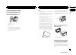
Section Connecting the units Connecting the units 01 Connecting the power cord English Navigation system (AVIC-F250 (sold separately)) 26 pin cable (Supplied with navigation unit) Insert the 26 pin cable in the direction indicated in the figure. 4m Please contact your dealer to inquire about the connectable navigation unit. This product Microphone Microphone input Fuse (10 A) Note: Depending on the kind of vehicle, the function of 2* and 4* may be different.
Section Connecting the units 01 Connecting the units When connecting to separately sold power amp When connecting the external video component and the display Rear output Front output External video component (sold separately) This product Power amp (sold separately) To front output Subwoofer output To subwoofer output Audio inputs (REAR AUDIO INPUT R) Power amp (sold separately) To rear output 10 cm Power amp (sold separately) To audio outputs RCA connector Connect with RCA cables (sold s
Section Connecting the units When the shift lever is switched to REVERSE (R), the display on this unit automatically switches to the rear view image. You need to set the Camera Polarity properly in the system menu. You can also switch the rear view image by pressing the touch panel key. For details, refer to operation manual. WARNING USE INPUT ONLY FOR REVERSE OR MIRROR IMAGE REAR VIEW CAMERA. OTHER USE MAY RESULT IN INJURY OR DAMAGE. CAUTION ! You must use a camera which outputs mirror reversed images.
Section Connecting the units 01 iPod with 30-pin connector When connecting with optional CD-IU201V cable Connecting the units When connecting with optional CD-IU201S cable This product USB/iPod input 1 Android When connecting the Androidä device with MHL port When connecting the Android device with HDMI port USB/iPod input 1 HDMI input USB/iPod input 1 USB/iPod input 2 Remove the cover before use.
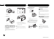
Section Connecting the units Installation 01 02 Installing the HDMI cable holder 3 — it may interfere with operation of the vehicle. — it may cause injury to a passenger as a result of a sudden stop. % Position the HDMI cable holder to insert its two lower tabs into the groove of this product, and then tighten the screw (3 mm × 5 mm) to fix the HDMI cable holder.
Section Installation 02 Installation Removing the unit 1 1 Installing the microphone Remove the trim ring. CAUTION It is extremely dangerous to allow the microphone lead to become wound around the steering column or shift lever. Be sure to install the unit in such a way that it will not obstruct driving. 2 1 Dashboard 2 Holder (factory-supplied part) 2 2 Note Install the microphone in a position and orientation that will enable it to pick up the voice of the person operating the system.
Section Installation 02 1 English 2 Install the microphone on the steering column. 1 2 2 1 Microphone clip 2 Clamp Use separately sold clamps to secure the lead where necessary inside the vehicle. When installing the microphone on the steering column 1 Detach the microphone base from the microphone clip. To detach the microphone base from the microphone clip, slide the microphone base. 1 3 1 Double-sided tape 2 Install the microphone on the rear side of the steering column.
Section Connexion des appareils 01 ATTENTION ! Pour éviter le risque d’accident et une violation potentielle des lois applicables, l’écran du siège avant ne doit en aucun cas être regardé pendant la conduite du véhicule. En outre, les écrans arrière ne doivent pas être placés dans un endroit où ils constituent visiblement une distraction pour le conducteur.
Section Connexion des appareils Connexion des appareils 01 Connexion du cordon d’alimentation Câble 26 broches (fourni avec l’unité de navigation) Unité de navigation (AVIC-F250 (vendue séparément)). Remarque: En fonction du type de véhicule, la fonction de 2* et de 4* peut différer. Sans ce cas, assurez-vous de connecter 1* à 4* et 3* à 2*. 4m Insérez le câble 26 broches dans la direction indiquée sur la figure.
Section Connexion des appareils 01 Connexion des appareils Lors de la connexion à un amplificateur de puissance vendu séparément Sortie arrière Sortie avant Lors de la connexion du composant vidéo externe et de l’écran Appareil vidéo externe (vendu séparément) Cet appareil Amplificateur de puissance (vendu séparément) À la sortie avant À la sortie arrière Sortie du caisson de grave Entrée audio (REAR AUDIO INPUT R) Amplificateur de puissance (vendu séparément) Amplificateur de puissance (vendu sé
Section Connexion des appareils Lors de la connexion à une caméra de vue arrière Entrée de la caméra de recul (R.C IN) Cet appareil iPod avec connecteur Lightning Lors de la connexion avec le câble Lightning vers USB Entrée USB/iPod 2 Retirez le couvercle avant utilisation. Reportez-vous à Entrée USB/iPod 1 et Entrée USB/iPod 2 Câble à fiches Cinch (RCA) (vendu séparément) ATTENTION PRÉCAUTION ! Vous devez utiliser une caméra qui génère des images inversées (images miroir).
Section Connexion des appareils 01 iPod avec connecteur 30 broches Lors de la connexion avec le câble CD-IU201V en option Connexion des appareils Lors de la connexion avec le câble CD-IU201S en option Entrée USB/iPod 1 Android Lors de la connexion d’un périphérique Androidä au port MHL Lors de la connexion d’un périphérique Android au port HDMI Cet appareil Entrée USB/iPod 1 Entrée USB/iPod 1 Entrée HDMI Entrée USB/iPod 2 Retirez le couvercle avant utilisation.
Section Connexion des appareils Installation 01 02 Installation du support de câble HDMI 2 1 3 3 4 1 2 3 4 ! Support de câble HDMI Vis (3 mm × 5 mm) Patte Rainure Utilisez le support de câble HDMI lorsque vous connectez cet appareil à l’aide du kit de connexion aux applications (CD-IH202/CDAH200) vendu séparément. ! Ne saisissez jamais le support avec force ou n’exercez aucune force excessive dessus lors du retrait ou de l’installation. — il peut interférer avec l’utilisation du véhicule.
Section Installation 02 Installation avec le support 1 Installez le support dans le tableau de bord. Une fois le support installé dans le tableau de bord, sélectionnez et courber les pattes en fonction de l’épaisseur du tableau de bord. (Fixez cet appareil aussi fermement que possible à l’aide des pattes supérieures et inférieures. Afin de fixer fermement l’appareil, courbez les pattes de 90 degrés.
Section Installation 02 2 Installez le microphone sur la colonne de direction. 1 1 Français 2 2 1 Clip microphone 2 Serre-fils Utilisez des serre-fils vendus séparément pour fixer le fil là où c’est nécessaire dans le véhicule. Si vous installez le microphone sur la colonne de direction 1 Détachez la base pour microphone du clip microphone. Pour détacher la base pour microphone du clip microphone, faites-la glisser.
Sezione Collegamento delle unità ATTENZIONE F O Con posizione ACC STAR 18 Importante ! Non è possibile installare questa unità in un veicolo che non dispone della posizione ACC (accessoria) per l’interruttore della chiave di avviamento. N ! PIONEER non raccomanda di installare o effettuare interventi di manutenzione sull’unità display da soli. L’installazione o la manutenzione del prodotto può esporre al rischio di scosse elettriche o altri pericoli.
Sezione Collegamento delle unità Collegamento delle unità 01 Collegamento del cavo di alimentazione Cavo con spine da 26 contatti (in dotazione all’unità di navigazione) Unità di navigazione (AVIC-F250 (in vendita a parte)). Per informazioni sugli apparecchi di navigazione collegabili si prega di rivolgersi al proprio rivenditore. Nota: In funzione del tipo di veicolo le funzione di 2* e di 4* potrebbe differire. In tal caso collegare 1* a 4* e 3* a 2*.
Sezione Collegamento delle unità 01 Collegamento delle unità Quando l’unità viene collegata a un amplificatore di potenza venduto a parte Collegamento di un componente video esterno e del display Componente video esterno (venduto a parte) Uscita posteriore Uscita anteriore Questo apparecchio Amplificatore di potenza (venduto a parte) All’uscita anteriore (REAR AUDIO INPUT R) Ingresso audio Amplificatore di potenza (venduto a parte) All’uscita posteriore Uscita per subwoofer Ingresso audio Ampli
Sezione Collegamento delle unità Collegamento a una telecamera per retromarcia Quando viene inserita la RETROMARCIA (R), il display passa automaticamente all’immagine della telecamera per retromarcia. È necessario impostare Camera Polarity correttamente nel menu di sistema. È inoltre possibile cambiare l’immagine della telecamera per retromarcia toccando il tasto sul touch panel. Per ulteriori dettagli, vedere il manuale d’istruzioni. Collegamento delle unità Ingresso alla videocamera di retromarcia (R.
Sezione Collegamento delle unità 01 iPod con connettore da 30 pin Collegamento con il cavo opzionale CD-IU201V Collegamento delle unità Collegamento con il cavo opzionale CD-IU201S Ingresso 1 USB/iPod Android Collegamento del dispositivo Androidä alla porta MHL Collegamento del dispositivo Android alla porta HDMI Ingresso 1 USB/iPod Questo apparecchio Ingresso 1 USB/iPod Ingresso 2 USB/iPod Rimuovere il coperchio prima dell’uso.
Sezione Collegamento delle unità Installazione 01 02 Installazione del supporto del cavo HDMI % Collocare il supporto del cavo HDMI in modo che le due linguette inferiori si inseriscano nelle fessure del prodotto, quindi serrare la vite (3 mm × 5 mm) per fissare il supporto del cavo HDMI.
Sezione Installazione 02 Installazione Installazione utilizzando il supporto Installazione utilizzando i fori delle viti ai lati dell’unità 1 Installare il supporto nel cruscotto. Dopo aver inserito il supporto nel cruscotto, scegliere e piegare le linguette in modo che corrispondano allo spessore del materiale del cruscotto. (Installare l’unità utilizzando le linguette superiori e inferiori in modo che sia fissata il più saldamente possibile. Per un montaggio sicuro, piegare le linguette a 90 gradi).
Sezione Installazione 02 2 Installare il microfono sul piantone dello sterzo. 1 1 2 2 Installazione del microfono sul piantone dello sterzo 1 Scollegare la base del microfono dalla clip del microfono. Per scollegare la base del microfono dalla clip, far scorrere la base del microfono. 1 Italiano 1 Clip del microfono 2 Morsetto Utilizzare i morsetti venduti separatamente per assicurare il cavo, ove necessario, all’interno del veicolo.
Sección Conexión de las unidades PRECAUCIÓN F O Posición ACC STAR 26 Importante ! No es posible instalar esta unidad en un vehículo con una llave de encendido que no tenga la posición ACC (accesorio). N ! PIONEER no recomienda que instale o repare la unidad de display usted mismo. La instalación o reparación del producto puede exponerle a descargas eléctricas u otros riesgos.
Sección Conexión de las unidades Conexión de las unidades 01 Conexión del cable de alimentación Cable de 26 clavijas (Suministrado con la unidad de navegación) Unidad de navegación (AVIC-F250 (vendida separadamente)). Póngase en contacto con su revendedor para cuestiones sobre la unidad de navegación que puede conectarse. 4m Inserte el cable de 26 clavijas en la dirección indicada en la figura. Nota: Dependiendo del tipo de vehículo, la función de 2* y 4* puede ser diferente.
Sección Conexión de las unidades 01 Conexión de las unidades Conexión a un amplificador de potencia comprado por separado Conexión con el componente de vídeo externo y el display Salida trasera Salida delantera Este producto Componente de vídeo externo (vendido separadamente) Amplificador de potencia (vendido separadamente) A la salida delantera Entrada de audio Salida de altavoz de subgraves (REAR AUDIO INPUT R) Amplificador de potencia (vendido separadamente) A la salida trasera Entrada de a
Sección Conexión de las unidades Conexión con una cámara retrovisora Cuando la palanca de cambios está en posición de MARCHA ATRÁS (R), la pantalla de la unidad se cambia automáticamente a la imagen retrovisora. Deberá configurar Camera Polarity correctamente en el menú del sistema. También puede cambiar la imagen retrovisora pulsando el teclado táctil. Si desea más información, consulte el manual de instrucciones. Conexión de las unidades Entrada para cámara de vista trasera (R.
Sección Conexión de las unidades 01 iPod con conector de 30 patillas Conexión con un cable CDIU201V opcional Conexión de las unidades Conexión con un cable CDIU201S opcional Entrada para USB/iPod 1 Android Al conectar el dispositivo Androidä al puerto MHL Al conectar el dispositivo Android al puerto HDMI Entrada de USB/iPod 1 Este producto Entrada HDMI Entrada de USB/iPod 1 Entrada para USB/iPod 2 Retire la cubierta antes de utilizar el dispositivo.
Sección Conexión de las unidades Instalación 01 02 Instalación del soporte de cable HDMI % Posicione el soporte de cable HDMI para insertar sus dos pestañas inferiores en la ranura de este producto y, a continuación, apriete el tornillo (3 mm × 5 mm) para fijar el soporte de cable HDMI.
Sección Instalación 02 Instalación Extracción de la unidad 1 1 Retire el anillo de guarnición. Instalación del micrófono PRECAUCIÓN Es muy peligroso que el cable del micrófono se enrolle alrededor de la columna de dirección o la palanca de cambios. Asegúrese de instalar la unidad de tal forma que no dificulte la conducción.
Sección Instalación 02 2 Instale el micrófono en la columna de dirección. 1 1 2 2 1 Pinza 2 Abrazadera Use las abrazaderas compradas por separado para fijar el cable en los lugares del interior del vehículo donde sea necesario. 1 Suelte la base del micrófono de la abrazadera del micrófono. Para soltar la base del micrófono de la abrazadera del micrófono, deslice la base del micrófono.
Abschnitt Anschließen der Geräte VORSICHT F O Zündung mit Position ACC STAR 34 Wichtig ! Dieses Gerät kann nicht in Fahrzeugen installiert werden, die am Zündschalter keine Position ACC aufweisen. N ! PIONEER empfiehlt Ihnen, die Installation und Wartung des Displays nicht selbst vorzunehmen. Bei der Installation und Wartung des Produkts setzen Sie sich ggf. der Gefahr eines elektrischen Schlags bzw. anderen Gefahren aus.
Abschnitt Anschließen der Geräte Anschließen der Geräte 01 Anschluss des Stromkabels 26-Pin-Kabel (mit dem Navigationsgerät mitgeliefert) Navigationsgerät (AVIC-F250 (getrennt erhaltlich)). Für weitere Informationen zu den Navigationsgeräten, die angeschlossen werden können, wenden Sie sich bitte an Ihren Fachhändler. Hinweis: Je nach Art des Fahrzeugs besitzen 2* und 4* u. U. unterschiedliche Funktionen. Verbinden Sie in einem solchen Fall 1* mit 4* und 3* mit 2*.
Abschnitt Anschließen der Geräte 01 Anschließen der Geräte Bei Anschluss an einen separat erhältlichen Leistungsverstärker Bei Anschluss der externen Videokomponente mit dem Display Hinterer Ausgang Vorderer Ausgang Dieses Produkt Externe Video- Komponente (getrennt erhältlich) Leistungsverstärker (getrennt erhältlich) Zum vorderen Ausgang Audio-Eingang Leistungsverstärker (getrennt erhältlich) Zum hinteren Ausgang SubwooferAusgang (REAR AUDIO INPUT R) Audio-Eingang 10 cm Leistungsverstärker (
Abschnitt Anschließen der Geräte Bei Anschluss mit einer Heckbildkamera Die Anzeige dieses Geräts wechselt automatisch zum Heckbild, wenn Sie den Schalthebel in die Position REVERSE (R) stellen. Sie müssen die Einstellung Camera Polarity korrekt im Systemmenü einrichten. Sie können auch durch die Berührung der Sensortaste auf das Heckbild umschalten. Details finden Sie in der Bedienungsanleitung. Anschließen der Geräte Rückwärtskamera-Eingang (R.
Abschnitt Anschließen der Geräte 01 iPod mit 30-poligem Anschluss Bei Anschluss mit einem zusätzlichen CD-IU201V Kabel Anschließen der Geräte Bei Anschluss mit einem zusätzlichen CD-IU201S Kabel USB/iPod-Eingang 1 Android Beim Anschluss eines AndroidäGeräts mit MHL-Port Beim Anschluss eines AndroidGeräts mit HDMI-Port USB/iPod-Eingang 1 Dieses Produkt HDMI-Eingang USB/iPod-Eingang 1 USB/iPod-Eingang 2 Entfernen Sie die Abdeckung vor dem Gebrauch.
Abschnitt Anschließen der Geräte Installation 01 02 Installieren des HDMI-Kabelhalters % Positionieren Sie den HDMI-Kabelhalter so, dass seine zwei unteren Klammern in die Nute dieses Produkts passen, und ziehen Sie dann die Schraube (3 mm × 5 mm) fest, um den HDMI-Kabelhalter zu fixieren. 2 1 3 3 4 1 2 3 4 ! — Orte, an denen das Gerät die Steuerung des Fahrzeugs behindern könnte. — Orte, an denen das Gerät die Insassen des Fahrzeugs im Anschluss an eine Schnellbremsung verletzen könnte.
Abschnitt Installation 02 Installation mit Halterung 1 Bringen Sie die Halterung am Armaturenbrett an. Wählen und biegen Sie nach dem Einsetzen der Halterung im Armaturenbrett die Klammern entsprechend der Dicke des Armaturenbrettmaterials. (Setzen Sie diese Einheit so fest wie möglich mithilfe der oberen und unteren Klammern ein. Biegen Sie die Klammern 90 Grad, um einen fest Halt zu gewährleisten.
Abschnitt Installation 02 2 Bringen Sie das Mikrofon an der Lenksäule an. 1 1 2 2 1 Mikrofonclip 2 Klammer Verwenden Sie nach Bedarf zusätzliche, separat erhältliche Klammern, um das Kabel im Fahrzeug zu sichern. Befestigen des Mikrofons an der Lenksäule 1 Lösen Sie die Mikrofon-Basisstation von der Mikrofonklammer. Um die Mikrofon-Basisstation vom Mikrofonclip abzunehmen, verschieben Sie die Basisstation. 1 Doppelseitiges Klebeband 2 Befestigen Sie das Mikrofon an der Rückseite der Lenksäule.
Hoofdstuk De toestellen aansluiten LET OP F O ACC-stand STAR 42 Belangrijk ! U kunt dit toestel niet installeren in een voertuig met een contactschakelaar zonder accessoirestand (ACC-stand). N ! PIONEER raad aan dat u dit toestel niet zelf installeert en onderhoudt. Bij de installatie en het onderhoud bestaat een risico op een elektrische schok en andere ongevallen. Laat alle installatie- en onderhoudswerkzaamheden aan dit toestel over aan een erkende installateur van Pioneer.
Hoofdstuk De toestellen aansluiten De toestellen aansluiten 01 De elektriciteitskabel aansluiten 26-pens kabel (meegeleverd met het navigatiesysteem) Navigatiesysteem (AVIC-F250 (los verkrijgbaar)). Neem contact op met uw dealer voor informatie over geschikte navigatiesystemen. Opmerking: Afhankelijk van het soort voertuig is het mogelijk dat de functies van 2* en 4* verschillen. Let er in een dergelijk geval op dat u 1* op 4* en 3* op 2* aansluit.
Hoofdstuk De toestellen aansluiten 01 De toestellen aansluiten Aansluiten op een los verkrijgbare versterker Achteruitgang Vooruitgang Het externe videoapparaat op het scherm aansluiten Externe videocomponent (los verkrijgbaar) Dit product Eindversterker (los verkrijgbaar) Naar vooruitgang Audio ingang Eindversterker (los verkrijgbaar) (REAR AUDIO INPUT R) Audio ingang Naar achteruitgang 10 cm Eindversterker (los verkrijgbaar) Subwoofer uitgang Naar subwoofer-uitgang (REAR AUDIO INPUT L) Naar
Hoofdstuk De toestellen aansluiten Aansluiten op een achteruitrijcamera Als u de versnellingspook in de stand ACHTERUIT (R) zet, wordt het beeld op dit toestel automatisch overgeschakeld naar de achteruitweergave. U moet ervoor zorgen dat Camera Polarity correct is ingesteld in het systeemmenu. U kunt ook naar de achteruitweergave overschakelen met de toets op het aanraakpaneel. Raadpleeg de handleiding voor meer informatie. De toestellen aansluiten Ingang achteruitkijk-camera (R.
Hoofdstuk De toestellen aansluiten 01 iPod met 30-pins aansluiting Aansluiten met de optionele kabel CD-IU201V De toestellen aansluiten Aansluiten met de optionele kabel CD-IU201S USB/iPod ingang 1 Android Als een Androidä-apparaat met MHL-poort wordt aangesloten Als een Android-apparaat met HDMI-poort wordt aangesloten USB/iPod ingang 1 Dit product HDMI-invoer USB/iPod ingang 1 USB/iPod ingang 2 Verwijder de afdekking voor gebruik.
Hoofdstuk De toestellen aansluiten Installatie 01 02 De HDMI-kabelhouder installeren % Plaats de HDMI-kabelhouder zo dat de twee lipjes onderaan in de groef van dit product vallen, en zet hem vast met de schroef (3 mm × 5 mm). 2 1 3 3 4 1 2 3 4 ! HDMI-kabelhouder Schroef (3 mm × 5 mm) Lipje Groef Gebruik de HDMI-kabelhouder als u dit product met de los verkrijgbare App Connectivity Kit (CD-IH202/CD-AH200) verbindt.
Hoofdstuk Installatie 02 Installatie Het toestel verwijderen 1 1 De microfoon installeren Verwijder de sierlijst. LET OP Het is zeer gevaarlijk om de microfoon zo te installeren dat het snoer zich om de stuurkolom of de versnellingspook kan wikkelen. Installeer het toestel zodanig dat het de besturing op geen enkele wijze kan belemmeren.
Hoofdstuk Installatie 02 2 Installeer de microfoon op de stuurkolom. 1 1 2 2 1 Microfoonklem 2 Klem Gebruik waar nodig los verkrijgbare klemmen om de kabel in het voertuig vast te zetten. Als u de microfoon op de stuurkolom installeert 1 Maak het microfoonstatief los van de microfoonklem. Schuif het microfoonstatief om het los te maken van de microfoonklem. 1 3 1 Dubbelzijdige tape 2 Installeer de microfoon achter op de stuurkolom.
Nl 50
Nederlands Nl 51 51
PIONEER CORPORATION 1-1, Shin-ogura, Saiwai-ku, Kawasaki-shi, Kanagawa 212-0031, JAPAN PIONEER ELECTRONICS (USA) INC. P.O. Box 1540, Long Beach, California 90801-1540, U.S.A. TEL: (800) 421-1404 PIONEER EUROPE NV Haven 1087, Keetberglaan 1, B-9120 Melsele, Belgium/Belgique TEL: (0) 3/570.05.11 PIONEER ELECTRONICS ASIACENTRE PTE. LTD. 253 Alexandra Road, #04-01, Singapore 159936 TEL: 65-6472-7555 PIONEER ELECTRONICS AUSTRALIA PTY. LTD.