CRD3650A_inst_cover 4/15/02 2:22 PM Page 3 DEUTSCH ITALIANO NEDERLANDS ENG/MASTER COVER 98 INST FRANÇAIS INSTALLATION MANUAL ENGLISH This product conforms to CEMA cord colors. Le code de couleur des câbles utilisé pour ce produit est conforme à CEMA.
CRD3650A_inst_001_030_Eng 4/15/02 2:17 PM Page 2 IMPORTANT INFORMATION ABOUT YOUR NEW DVD NAVIGATION UNIT AND THIS MANUAL • The Pioneer DVD Navigation Unit is intended solely as an aid to you in the operation of your car. It is not a substitute for your attentiveness, judgment and care while driving. • Do not use your navigation system to route you to emergency services such as hospitals or police stations. Not all emergency service facilities are contained in the map data.
CRD3650A_inst_001_030_Eng 4/15/02 2:17 PM Page 3 Contents Connecting the System ............................ 5 CAUTION ........................................................ 5 - Before installing the unit - To prevent damage - Parts supplied Connecting the system ...................................... 7 - Connecting to the display with 26-pin RGB input (AVH-P6400CD, AVH-P6400, etc.) - Connecting to the display with 20-pin RGB input Connecting the System (In case of a display sold in the market) ....
CRD3650A_inst_001_030_Eng 4/15/02 2:17 PM Page 4 IMPORTANT SAFEGUARDS PLEASE READ ALL OF THESE INSTRUCTIONS REGARDING YOUR DVD NAVIGATION UNIT AND RETAIN THEM FOR FUTURE REFERENCE 1. Read this manual fully and carefully before installing your DVD Navigation Unit. 2. Keep this manual handy for future reference. 3. Pay close attention to all warnings in this manual and follow the instructions carefully. 4. This unit is intended solely as an aid to you in the operation of your car.
CRD3650A_inst_001_030_Eng 4/15/02 2:17 PM Page 5 ENGLISH 7. As with any accessory in your car’s interior, the DVD Navigation Unit should not divert your attention from the safe operation of your car. If you experience difficulty in operating the system or reading the display, please make adjustments while safely parked. ESPAÑOL 8. Do not attempt to install or service your DVD Navigation Unit by yourself.
CRD3650A_inst_001_030_Eng 4/15/02 2:17 PM Page 6 Connecting the System CAUTION • Pioneer does not recommend that you install or service your DVD navigation unit yourself. Installing or servicing of the product may expose you to risk of electric shock or other hazards. Refer all installation and servicing of your navigation unit to authorized Pioneer service personnel. • Secure all wiring with cable clamps or electrical tape. Do not allow any bare wiring to remain exposed.
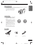
CRD3650A_inst_001_030_Eng 4/15/02 2:17 PM Page 7 Before installing the unit ENGLISH • This unit is for cars with a 12-volt battery and negative grounding. Before installing it in a recreational car, truck, or bus, check the battery voltage. • To avoid shorts in the electrical system, be sure to disconnect the (-) battery cable before beginning installation. ESPAÑOL O OF F O STAR STAR FRANÇAIS T T ACC position DEUTSCH ACC N F N • When disconnecting a connector, pull the connector itself.
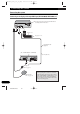
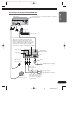
CRD3650A_inst_001_030_Eng 4/15/02 2:17 PM Page 8 Connecting the System Connecting the system Connecting to the display with 26-pin RGB input (AVH-P6400CD, AVH-P6400, etc.) Use this jack when connecting the CUE unit for obtaining traffic information. Power cord ☞ See pages 11-13. 26-pin RGB cable (supplied) (Ex. AVH-P6400CD, AVH-P6400) 6m (19ft 8in.) Microphone ☞ See page 27. When resetting AV Head Unit GPS antenna ☞ See page 22.
CRD3650A_inst_001_030_Eng 4/15/02 2:17 PM Page 9 Connecting to the display with 20-pin RGB input ENGLISH This product Use this jack when connecting the CUE unit for obtaining traffic information. ESPAÑOL Power cord ☞ See page 11-13. DEUTSCH Level Control This is used for adjusting output from Audio Output. If you turn it to the right, the volume increases, while turning it to the left reduces the volume.
CRD3650A_inst_001_030_Eng 4/15/02 2:17 PM Page 10 Connecting the System Connecting the System (In case of a display sold in the market) Use this jack when connecting the CUE unit for obtaining traffic information. Power cord ☞ See pages 11-13. Level Control This is used for adjusting output from Audio Output. If you turn it to the right, the volume increases, while turning it to the left reduces the volume.
CRD3650A_inst_001_030_Eng 4/15/02 2:17 PM Page 11 ENGLISH In order to output the image (RGB image) from RCA Video output (yellow) when performing navigation, switching the image output is required. 1. Park your car in a safe place, and pull the side brake. 2. Turn the power of the main unit off (cut off the engine). ESPAÑOL 3. While pressing (AUDIO) button on the bottom left of the numeric keypad of the Remote Controller, turn the ACC on (start the engine).
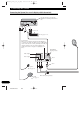
CRD3650A_inst_001_030_Eng 4/15/02 2:17 PM Page 12 Connecting the System Connecting the power cord (1) Speed detection circuit lead Connection method Pass the extension cord and the lead for the speed detection circuit through this hole. Car injection computer Connector Clamp firmly with needle-nosed pliers. Close the cover. Pink (CAR SPEED SIGNAL INPUT) Note: The position of the speed detection circuit depends on the car model. For details, consult the relevant documents from Pioneer.
CRD3650A_inst_001_030_Eng 4/15/02 2:17 PM Page 13 ENGLISH This product Note: ESPAÑOL Cords for this product and those for other products may be different colors even if they have the same function. When connecting this product to another product, refer to the supplied Installation manuals of both products and connect cords that have the same function. Power cord Black, Orange/white, Red, Yellow DEUTSCH ☞ See Page 13.
CRD3650A_inst_001_030_Eng 4/15/02 2:17 PM Page 14 Connecting the System Connecting the power cord (2) This product Note: Cords for this product and those for other products may be different colors even if they have the same function. When connecting this product to another product, refer to the supplied Installation manuals of both products and connect cords that have the same function. Power cord Black To car (metal) body.
CRD3650A_inst_001_030_Eng 4/15/02 2:17 PM Page 15 Installation ENGLISH CAUTION • Certain state laws may prohibit or restrict the placement and use of this system in your car. Please comply with all applicable laws and regulations regarding the use, installation, and operation of your navigation system. ESPAÑOL • Pioneer does not recommend that you install or service your DVD navigation unit yourself. Installing or servicing the product may expose you to risk of electric shock or other hazards.
CRD3650A_inst_001_030_Eng 4/15/02 2:17 PM Page 16 Installation To guard against electromagnetic interference • In order to prevent interference, set the following items as far as possible from the main unit of this Navigation System, other cables or leads: - TV antenna and antenna lead - FM, AM antenna and its lead - GPS antenna and its lead In addition you should lay each antenna lead as far as possible from other antenna leads. Do not bind them together, lay them together, or cross them.
CRD3650A_inst_001_030_Eng 4/15/02 2:17 PM Page 17 Installing the main unit ENGLISH Installation notes ESPAÑOL • Do not install the main unit in places where it may become subject to high temperatures or humidity, such as: * Places close to a heater outlet. * Places exposed to direct sunlight, such as on top of the dashboard or the rear shelf. * Places that may be splashed by rain, for example close to the door. • The installation strength will depend on the car model and the installation position.
CRD3650A_inst_001_030_Eng 4/15/02 2:17 PM Page 18 Installation Parts supplied Main unit Binding screw (5 × 6 mm) (4 pcs.) Tapping screw (6 × 16 mm) (4 pcs.) Mounting angle (2 pcs.) 17 ENG/MASTER 96 18 Flush surface screw (5 × 6 mm) (4 pcs.
CRD3650A_inst_001_030_Eng 4/15/02 2:17 PM Page 19 ENGLISH CAUTION • Install with the left and right sides of the DVD Navigation Unit perpendicular or parallel to your car’s direction of travel. Do not install diagonally to your car’s direction of travel or the current location will be displayed incorrectly.
CRD3650A_inst_001_030_Eng 4/15/02 2:17 PM Page 20 Installation When installing the main unit inside the trunk, on the floor under a seat, etc., using tapping screws 1. Fit mounting angles to the sides of the main unit. Use the following holes on the mounting angles.
CRD3650A_inst_001_030_Eng 4/15/02 2:17 PM Page 21 2. Fix to the floor with tapping screws. ENGLISH Tapping screw ESPAÑOL Floor Drill 4 to 4.5 mm diameter holes. DEUTSCH CAUTION • Before drilling any mounting holes, confirm that the screws will not interfere with any of the car’s operating systems (such as the fuel line, brake lines, electrical wiring, etc.).
CRD3650A_inst_001_030_Eng 4/15/02 2:17 PM Page 22 Installation DIN Rear-mount: Installation using the screw holes on the side of the unit • Fastening the unit to the factory radio mounting bracket. Select a position where the screw holes of the bracket and the screw holes of the head unit become aligned (are fitted), and tighten the screws at 2 places on each side. Use either binding screws (5 × 6 mm) or flush surface screws (5 × 6 mm), depending on the shape of the screw holes in the bracket.
CRD3650A_inst_001_030_Eng 4/15/02 2:17 PM Page 23 Installing the GPS antenna ENGLISH CAUTION • Do not cut the GPS antenna lead to shorten it or use an extension to make it longer. Altering the antenna cable could result in a short circuit. ESPAÑOL Installation notes Dashboard DEUTSCH • The antenna should be installed on a level surface where radio waves will be blocked as little as possible. Radio waves cannot be received by the antenna if reception from the satellite is blocked.
CRD3650A_inst_001_030_Eng 4/15/02 2:17 PM Page 24 Installation Parts supplied GPS antenna Metal sheet Clamp (5 pcs.) Waterproof pad When installing the antenna inside the car (on the dashboard or rear shelf) Affix the metal sheet on as level a surface as possible where the GPS antenna faces outside the window. Place the GPS antenna on the metal sheet. (The GPS antenna is fastened with its magnet.) GPS antenna Metal Sheet Peel off the protective sheet on the rear.
CRD3650A_inst_001_030_Eng 4/15/02 2:17 PM Page 25 When installing the antenna outside the car (on the body) ENGLISH Put the GPS antenna in a position as level as possible, such as on the roof or trunk lid. (The GPS antenna is fastened with a magnet.) GPS antenna ESPAÑOL When routing the lead in from the top of the door DEUTSCH Make a U-shaped loop in the lead on the outside to prevent rainwater from flowing along the lead into the interior of the car.
CRD3650A_inst_001_030_Eng 4/15/02 2:17 PM Page 26 Installation Installing the Remote controller Parts supplied Remote controller Alkaline battery (UM-4, AAA, LR03 1.5 V) (2 pcs.) Holder Double-sided tape (large) Loading the batteries Remove the battery cover, and insert two alkaline (UM-4, AAA, LR03, 1.5V) batteries. For details, see “Hardware Manual”. CAUTION • Take care to insert the batteries the right way round as shown by the + and marks in the diagram. • Do not mix new batteries with old.
CRD3650A_inst_001_030_Eng 4/15/02 2:17 PM Page 27 When installing with double-sided tape ENGLISH Attach the Holder using the double-sided tape (large) included in the set.
CRD3650A_inst_001_030_Eng 4/15/02 2:17 PM Page 28 Installation Installing the microphone Installation notes • Install the microphone in a position and orientation that will enable it to pick up well the voice of the person operating the system by voice. Parts supplied Microphone Microphone clip 27 ENG/MASTER 96 28 Double-sided tape (small) Clamp (5 pcs.
CRD3650A_inst_001_030_Eng 4/15/02 2:17 PM Page 29 When installing the microphone on the sun visor ENGLISH 1. Install the microphone on the microphone clip. Microphone ESPAÑOL Microphone clip 2. Install the microphone clip on the sun visor. With the sun visor up, install the microphone clip. (Lowering the sun visor reduces the recognition rate for voice operations.) DEUTSCH Microphone clip FRANÇAIS Clamps Use clamps to secure the lead where necessary inside the car.
CRD3650A_inst_001_030_Eng 4/15/02 2:17 PM Page 30 Installation When installing the microphone on the steering column 1. Install the microphone on the microphone clip. Fit the microphone lead into the groove. Microphone Microphone clip 2. Install the microphone clip on the steering column. Double-sided tape Install the microphone clip on the rear side of the steering column. Clamps Use clamps to secure the lead where necessary inside the car.
CRD3650A_inst_001_030_Eng 4/15/02 2:17 PM Page 31 After installing the unit 1. Reconnecting the battery. ENGLISH First, double-check that all connections are correct and that the unit is installed correctly. Reassemble all car components that you previously removed. Then reconnect the negative (–) cable to the negative (–) terminal of the battery. 2. Start the engine. 3. Press the reset button on the main unit. Press the reset button on the main unit using a pointed object such as the point of a pen.
CRD3650A_inst_032_061_FRE 4/15/02 2:18 PM Page 32 INFORMATION IMPORTANTE A PROPOS DE VOTRE UNITÉ DE NAVIGATION DVD ET DE CE MANUEL • Cette unité de navigation DVD Pioneer est destinée uniquement à vous aider dans la conduite de votre véhicule. En aucun cas, elle n’autorise un relâchement de votre attention, de votre jugement et de votre vigilance pendant la conduite. • N’utilisez pas cette unité de navigation DVD pour des services d’urgence comme des hôpitaux ou des postes de police.
CRD3650A_inst_032_061_FRE 4/15/02 2:18 PM Page 33 Table des matières VEUILLEZ LIRE TOUTES LES EXPLICATIONS RELATIVES À VOTRE UNITÉ DE NAVIGATION DVD ET LES CONSERVER POUR VOUS Y RÉFÉRER ÉVENTUELLEMENT PAR LA SUITE .......................................... 3 DEUTSCH ATTENTION .................................................... 5 - Avant de raccorder l’appareil - Pour éviter des dégâts - Pièces fournies Branchement du système ....................................
CRD3650A_inst_032_061_FRE 4/15/02 2:18 PM Page 34 IMPORTANTES MESURES DE SECURITE VEUILLEZ LIRE TOUTES LES EXPLICATIONS RELATIVES À VOTRE UNITÉ DE NAVIGATION DVD ET LES CONSERVER POUR VOUS Y RÉFÉRER ÉVENTUELLEMENT PAR LA SUITE 1. Lisez attentivement toute cette brochure avant d’installer votre unité de navigation DVD. 2. Conservez ce manuel à portée de la main pour vous y référer ultérieurement. 3. Tenez compte de tous les avertissements formulés dans ce manuel et respectez soigneusement les consignes. 4.
CRD3650A_inst_032_061_FRE 4/15/02 2:18 PM Page 35 ENGLISH 7. Comme tout autre accessoire de l’habitacle, l’unité de navigation DVD ne doit pas détourner votre attention et nuire à la sécurité de la conduite. Si vous éprouvez des difficultés à utiliser le système ou à lire l’écran, effectuez les réglages nécessaires après vous être garé dans un endroit sûr. FRANÇAIS 8. N’essayez pas d’installer ou d’entretenir vous-même votre unité de navigation DVD.
CRD3650A_inst_032_061_FRE 4/15/02 2:18 PM Page 36 Branchement du système ATTENTION • Pioneer déconseille d’installer ou d’entretenir vous-même votre unité de navigation DVD. Ces travaux comportent des risques d’électrocution et d’autres dangers. Confiez l’installation et l’entretien à un personnel de service Pioneer qualifié. • Immobilisez tous les fils avec des colliers ou des serre-câbles. Ne laissez aucun fil à nu.
CRD3650A_inst_032_061_FRE 4/15/02 2:18 PM Page 37 Avant de raccorder l’appareil ENGLISH • Cet appareil est destiné aux véhicules avec une batterie de 12 V, avec pôle négatif à la masse. Avant de l’installer dans un véhicule de loisir, un camion ou un car, vérifiez la tension de la batterie. • Afin d’éviter tout risque de court-circuit, débranchez le câble de la borne négative (-) de la batterie avant de commencer la pose.
CRD3650A_inst_032_061_FRE 4/15/02 2:18 PM Page 38 Branchement du système Branchement du système Branchement à l’écran à l’aide du câble 26 broches RVB d’entrée (AVH-P6400CD, AVH-P6400, etc.) Ce produit Utilisez cette prise pour connecter l’unité CUE afin d’obtenir les informations sur le trafic. Cordon d’alimentation ☞ Cf. pages 11-13. Câble 26 broches RVB (fourni) (Ex. AVH-P6400CD, AVH-P6400) 6m Microphone ☞ Cf. page 27. Antenne GPS ☞ Cf. page 22.
CRD3650A_inst_032_061_FRE 4/15/02 2:18 PM Page 39 Branchement à l’écran à l’aide du câble 20 broches RVB d’entrée ENGLISH Ce produit Utilisez cette prise pour connecter l’unité CUE afin d’obtenir les informations sur le trafic. FRANÇAIS Cordon d’alimentation DEUTSCH ☞ Cf. pages 11-13. FRANÇAIS Commande de niveau Cette commande est utilisée pour régler la sortie audio. Tournez vers la droite pour augmenter, ou respectivement vers la gauche pour diminuer le volume.
CRD3650A_inst_032_061_FRE 4/15/02 2:18 PM Page 40 Branchement du système Branchement du système (dans le cas d’un écran disponible sur le marché) Utilisez cette prise pour connecter l’unité CUE afin d’obtenir les informations sur le trafic. Cordon d’alimentation ☞ Cf. pages 11-13. Commande de niveau Cette commande est utilisée pour régler la sortie audio. Tournez vers la droite pour augmenter, ou respectivement vers la gauche pour diminuer le volume.
CRD3650A_inst_032_061_FRE 4/15/02 2:18 PM Page 41 ENGLISH Pour obtenir l’image (image RGB) sur la sortie vidéo RCA (jaune) lorsque la fonction de navigation est activée, il faut commuter la sortie d’image. 1. Garez votre véhicule en respectant les règles de sécurité et tirez le frein de stationnement. 2. Coupez l’alimentation de l’unité principale (coupez le moteur). FRANÇAIS 3.
Branchement du système Branchement du cordon d’alimentation (1) Conducteur de circuit de détection de vitesse Méthode de connexion Passez le cordon-rallonge et le fil pour le circuit de détection de vitesse par ce trou. Ordinateur d’injection Connecteur Serrez fermement avec une pince à mâchoires pointues. Fermez le couvercle. Rose (Entrée du signal de vitesse de voiture) Remarque: La position du circuit de détection de vitesse dépend du modèle du véhicule.
CRD3650A_inst_032_061_FRE 4/15/02 2:18 PM Page 43 ENGLISH Remarque: Ce produit FRANÇAIS Les câbles de ce produit et ceux d’autres produits peuvent fort bien ne pas être de la même couleur bien que remplissant la même fonction. Pour relier ce produit à un autre produit, utilisez le manuel d’installation de chacun et effectuez les raccordements en ne tenant compte que de la fonction de chaque câble. Cordon d’alimentation Noir, Orange/blanc, Rouge, Jaune ☞ Cf. page 13.
CRD3650A_inst_032_061_FRE 4/15/02 2:18 PM Page 44 Branchement du système Branchement du cordon d’alimentation (2) Ce produit Remarque: Les câbles de ce produit et ceux d’autres produits peuvent fort bien ne pas être de la même couleur bien que remplissant la même fonction. Pour relier ce produit à un autre produit, utilisez le manuel d’installation de chacun et effectuez les raccordements en ne tenant compte que de la fonction de chaque câble.
CRD3650A_inst_032_061_FRE 4/15/02 2:18 PM Page 45 Installation ENGLISH ATTENTION • Les lois de certains états peuvent interdire ou limiter l’installation et l’emploi de ce système dans les voitures. Conformez-vous à toutes les lois et réglementations en vigueur sur l’installation, l’utilisation et le fonctionnement du système de navigation.
CRD3650A_inst_032_061_FRE 4/15/02 2:18 PM Page 46 Installation Pour protéger le système de navigation contre les parasites électromagnétiques • Pour éviter tout parasite, placez les éléments suivants le plus loin possible de l’unité principale de l’unité de navigation DVD, d’autres câbles ou cordons : - Antenne TV et cordon d’antenne - Antenne FM, AM et son cordon - Antenne GPS et son cordon Placez également chaque cordon d’antenne le plus loin possible des autres cordons d’antenne.
CRD3650A_inst_032_061_FRE 4/15/02 2:18 PM Page 47 Installation de l’unité principale ENGLISH Remarques sur l’installation FRANÇAIS • N’installez pas l’unité principale à un endroit où elle serait soumise à une forte température ou à l’humidité, tel que: * Près d’une bouche du chauffage du véhicule. * En plein soleil, comme sur le dessus de la planche de bord ou de la lunette arrière. * Evitez un endroit où l’unité peut être mouillée par la pluie, comme près d’une porte.
CRD3650A_inst_032_061_FRE 4/15/02 2:18 PM Page 48 Installation Pièces fournies Unité principale Vis taraudeuse (6 × 16 mm) (4 pièces) Applique de montage (2 pièces) 17 ENG/MASTER 96 Vis de serrage (5 × 6 mm) (4 pièces) 48 Vis à tête plate (5 × 6 mm) (4 pièces)
CRD3650A_inst_032_061_FRE 4/15/02 2:18 PM Page 49 ENGLISH ATTENTION • Effectuez l’installation avec les côtés gauche et droit de l’unité de navigation DVD perpendiculairement ou parallèlement au sens de déplacement du véhicule. N’effectuez pas d’installation en diagonale par rapport au sens de déplacement du véhicule sinon la position actuelle ne s’affichera pas correctement.
CRD3650A_inst_032_061_FRE 4/15/02 2:18 PM Page 50 Installation Installation dans le coffre, sur le tapis, sous un siège, etc. avec les vis taraudeuses 1. Fixez les appliques de montage sur les deux côtés de l’unité principale. Utilisez les trous indiqués sur les appliques de montage.
CRD3650A_inst_032_061_FRE 4/15/02 2:18 PM Page 51 2. Fixez l’unité sur le plancher avec les vis taraudeuses. ENGLISH Vis taraudeuse FRANÇAIS Plancher Forez des trous de 4 à 4,5 mm de diamètre. DEUTSCH ATTENTION • Avant de forer des trous, assurez-vous que les vis ne gêneront aucun organe du véhicule (canalisations de carburant, circuits de freinage, câbles d’alimentation, etc.).
CRD3650A_inst_032_061_FRE 4/15/02 2:18 PM Page 52 Installation Montage DIN arrière : Installation en utilisant les trous de vis sur les côtés de l’appareil • Fixation de l’appareil au support de montage installée par le constructeur. Choisir la position selon laquelle les orifices de vis du support et ceux des vis de l’appareil principal sont alignés (correspondent) et serrer les vis sur 2 endroits de chaque côté.
CRD3650A_inst_032_061_FRE 4/15/02 2:18 PM Page 53 Installation de l’antenne GPS ENGLISH ATTENTION • Ne coupez pas le câble de l’antenne GPS et n’utilisez pas un prolongateur pour l’allonger car une telle modification pourrait provoquer un court-circuit. FRANÇAIS Remarques sur l’installation DEUTSCH • L’antenne doit être installée sur une surface à niveau où les ondes radio sont bloquées le moins possible.
CRD3650A_inst_032_061_FRE 4/15/02 2:18 PM Page 54 Installation Pièces fournies Antenne GPS Plaque métallique Serre-fils (5 pièces) Coussin étanche Installation de l’antenne dans le véhicule (sur planche de bord ou lunette arrière) Fixez la plaque métallique sur une surface aussi plate que possible où l’antenne GPS sera dirigée vers une vitre. Posez l’antenne GPS sur la plaque métallique. (L’antenne GPS est immobilisée par son propre aimant.
CRD3650A_inst_032_061_FRE 4/15/02 2:18 PM Page 55 Installation de l’antenne à l’extérieur du véhicule (sur la carrosserie) ENGLISH Posez l’antenne GPS sur une surface aussi plate que possible, telle que le toit ou le capot du coffre. (L’antenne GPS est immobilisée par son propre aimant.) Antenne GPS FRANÇAIS Effectuez une boucle en U avec le câble à l’extérieur pour éviter une infiltration d’eau dans l’habitacle.
CRD3650A_inst_032_061_FRE 4/15/02 2:18 PM Page 56 Installation Installation de la télécommande Pièces fournies Télécommande Pile alcaline (UM-4, AAA, LR03, 1,5 V) (2 pièces) Support Bande adhésive double face (grande) Insertion des piles Retirez le capot du logement des piles et insérez deux piles alcalines (UM-4, AAA, LR03, 1,5V). Pour plus de détail, voir “Manuel de fonctionnement ”. ATTENTION • Veillez à insérer les piles dans la bonne position, comme illustré par les signes + et - sur le schéma.
CRD3650A_inst_032_061_FRE 4/15/02 2:18 PM Page 57 En cas d'installation avec bande adhésive double face ENGLISH Fixez le support à l'aide de la bande adhésive double face (large) incluse dans le nécessaire.
CRD3650A_inst_032_061_FRE 4/15/02 2:18 PM Page 58 Installation Installation du microphone Remarques sur l’installation • Installez et orientez le microphone à un endroit où il pourra bien capter la voix de la personne qui commande le système par la voix.
CRD3650A_inst_032_061_FRE 4/15/02 2:18 PM Page 59 Installation du microphone sur le pare-soleil ENGLISH 1. Fixez le microphone sur l’attache fournie. FRANÇAIS Microphone Attache 2. Fixez l’attache du microphone sur le pare-soleil. Le pare-soleil étant relevé, fixez l’attache du microphone. (Le taux de reconnaissance vocale diminue quand le pare-soleil est abaissé.) DEUTSCH Attache de microphone FRANÇAIS Serre-fils A utiliser pour fixer le fil conducteur aux endroits nécessaires dans le véhicule.
CRD3650A_inst_032_061_FRE 4/15/02 2:18 PM Page 60 Installation Installation du microphone sur la colonne de direction 1. Fixez le microphone sur l’attache fournie. Cheminez le fil du microphone dans la rainure. Microphone Attache 2. Fixez l’attache du microphone sur la colonne de direction. Bande adhésive double face Installez l’attache de microphone sur l’arrière de la colonne de direction. Serre-fils A utiliser pour fixer le fil conducteur aux endroits nécessaires dans le véhicule.
CRD3650A_inst_032_061_FRE 4/15/02 2:18 PM Page 61 Après installation de l’unité 1. Branchement de la batterie. ENGLISH Vérifiez une nouvelle fois que toutes les connexions ont été bien faites et que l’unité est correctement installée. Remontez tous les composants du véhicule qui ont été déposés, puis rebranchez le câble négatif (–) sur la borne négative (–) de la batterie. 2. Mettez le moteur en marche. 3. Appuyez sur la touche de réinitialisation de l’unité principale.
CRD3650A_inst_cover 4/15/02 2:22 PM Page 2 PIONEER CORPORATION 4-1, MEGURO 1-CHOME, MEGURO-KU, TOKYO 153-8654, JAPAN PIONEER ELECTRONICS (USA) INC. P.O. Box 1760, Long Beach, California 90801, U.S.A. TEL: (800) 421-1404 PIONEER EUROPE NV Haven 1087, Keetberglaan 1, B-9120 Melsele, Belgium TEL: (0) 3/570.05.11 PIONEER ELECTRONICS ASIACENTRE PTE. LTD. 253 Alexandra Road, #04-01, Singapore 159936 TEL: 65-472-1111 PIONEER ELECTRONICS AUSTRALIA PTY. LTD.