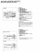
/oo. (v)proNeerl" Tlp Art ot Entertaiment ^ Service Manual 6 _EB q _f__l:iio :tr)lo6ao6tb .68 ORDERNO. it a5 RRV1O23 STEREOMULTI-PLAYCD CASSETTEDECKRECEIVER r; R.P7 4()M x R-P64olul x R-P34()M XR P7 4 o XR P6 4 o XR P3 4 o STEREOCD CASSETTEDECKRECEIVER I I I THISMANUALIS APPLICABLE TO THEFOLLOWING IVIODEL(SI AND TYPE(S}. r Typ.
XR-P74()M, XR-P64()M, XR-P34()M xR-P7 &, XR-pOaO, XR-P34() CHAPTER1 1.1 SAFETYINFORMATION This service manual is intended for quallfled service technicians; lt ls not meant tor the casual do-it-yourselfer. Oualified technicians have the necessary test equiprnent and tools, and have been trained to properly and safely repair complex products such as those covered by this manual. lmproperly performed repairs can adverselyaftoct ths.
XR-P74OM, XR-P64OM, XR-P34OM xR-P7 N, XR-P64(), XR-P34() (FOREUROPEANMODEL ONLY} AVATTAESSA JA SUOJALUKITUS OHITETTAESSA OL€T ALTTIINA NAKYMATToMALLE LASERSATEILYLLE A L A K A T S OS A T E E S E E N USYNIIG LASEESTRALING VED ABNING N A B S I K K E R H E D S A F B R Y D EEFREU D E A F F U N K T I O N U N D G A U D S A E T T E L S EF o R STFALING O E V I C EI N C L U O E SL A S E R O I O D EW H I C H E M I T S I N V I S I B L EI N F R A B E DB A D I A T I O N W I ] I C HI S D A N G E R O U T SO E Y E S T H
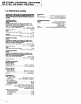
XR-P74()M, XR-P64()M, XR-P340M xR-P7 Q, XR-P64(), XR-P3@ 1.2 SPEC|F|CATIONS STEREOCD CASSETTE DECK RECEIVER/STEREO MULTI-PLAY CD CASSETIE DECK RECETVER:XRn 0 I x3'P, &NU XR-Pr6aO/XR-F6{!M/XR+AO/XRP3/('M CD Scction Type................................Compact discdigiral audiosystem WowandFluttsr................................ Limitol m66suremont G0.001%W.PEAK) or less(EIAJ) Ampliftcr scction Cassdte deck 3.ction
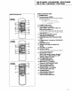
XR-P74OM, XR-P64OM, XR-P34OM )(R-P7 Q. XR-P6@, XR-P34O 1 . 3 P A N E LF A C I L I T I E S RECEIVER The XR-P340/XB-P340fi/ is 1ot eaurppedw n the butto4sOF a.
XR-P74()M, XR-P621()M, XR-P34()M xR-P7 &, XR-P64(), XR-P340 TAPEDECK TAPEDECK Q TAPEI ca$etto door q) TAPEI EJECTsoction (A) Q) TAPEll EJECTs.ction (A ) (4) TAPEll casscttodoor 6 fnPt 1/2 soloctor button @ DOLBY.NR B/C OFFbutron (XR-P74O/XRP?40Mand XR-P6/0/XR-P640M) Each lime this button is pressed, DOLBY NB settlng chanoesB*C*OFF. @' oor--ev.NRoN/OFFbutton(XR-P3/o/XRP3/0Monly) DOLEYNR sYstem Eachtime this buttonis pressed, turnsONandOFF.
XR-P74()M, XR-P64()M, XR-P340M xR-P7 N, XR-P640, XR-P34() REMOTECONTROLUN]T REMOTECONTROLUNIT O PowER butron @ Functionbutton (FUNCI Eachtimethis button is pressed,the function changesin the following sequence: + TAPE VIDEO/AUX TUNERBAND bufton @ TAPEop€ration buttons {SHIFTTAPE1,56s111 >>, Play < >, Stop r, Recpause a ll l To operate TAPE l. press the desired deck operation l.
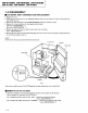
XR-P74()M, XR-P640M, XR-P34()M xF|-P7 40, XR-P640, XR-P34() 1.4 DISASSEMBLY AND REPLACEMENT T CD MECHAASSYDIAGNOSIS 1. Remove the cover. 2. OPEN the tray and lift the tray cap, pulling the bottom of the tray cap toward you. After removing the tray cap, CLOSE the tray. 3. Remove the VOL knob and 2 screws (BBZ30P080FZK)holding the VR assy in place. 4. Remove the 3 screws between the front Daneland the chassis. L/R sides: CBZ30P080FMC x2 Bottom side: BBZ30P080FZK x 1 5.
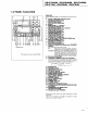
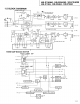
XR-P740M, XR-P640M, XR-P340M xR-P740, XR-P64{J--, XR-P34.o 1 . 5 B L O C KD I A G R A M XR--P64O\I, XR-P640 ONLY I ! -< ""n 30omv (XFI-P7401,( 7a0) 71nV (XR-P54O'{ E40) I I I POAER AI'IP I I I I S SP OUT I I REAR B\TFFER S VO-Lri€ 't r t I I lc21 03 l:oorntl! )cup740M xR-P74o o.LY c vo|-t.
XR-P740M, XR-P64()M, XR-P340M xR-P7 44, XR-P640, XR-P34() a Pin Functionof Power Amo Module Connector No. Name UO + 12V.M o 2 UNREG 12 3 AC Description + 12V separatesystemstabilizedoutput Unstabilized power input for - 12V I AC detecrioninput:for powerON/OFFandMUTE. o Stabilizedpower output for - 12V 4 tzv 5 MUTE vo 6 REF,GND I GND Ior protective circuit; referenceGND for short detection 7 BLOW I BLOW circuit extemal output; ON at :t0.5V or mo!e. 8 REG.
XR-P34()M XR-P740M, XR-P640M, xR-P7 40, XR-P64trJ_, XR-P340 1.6 IC INFORMATION c The information shown in the list is basic information and may not correspond exactly to that shown in the schematic diagrams. I rc9268F ilc84o1 : AF cD AssY) O X-A Modulation-TypeDA Converter with Built-in 8-fold OversamplingDigital Filter o PinAssignment(TopView) o Block Diagram LrcK MX MTA K EF rcK WX LrcX rcK EF WA - WX xo XI NX o Pin Function No.
XR-P740M, XR-P640M, XR-P340M xR-P7 40, XR-P6 Q, XR-P340 I PD4493A{tC19O1: DtSpLAyASSYfor MULTTCDI O System Control Micro-computer o PinAssignment(TopView) No. Name Function GO.
XR-P74()M, XR-P640M, XR-P34()M xR-P7 &, XR-P640, XR-P34() No. Name Function P30 44 P03 SENS uo I Description LSI operating status multi-mode iDput I Frame/syncMock input I Subcode synch SO + SI input AC I AC input REM I Remote control sigrralinput GFS No.
XR-P640M, XR-P340M XR-P7@M, xR-P7 &, XR-P64{J_, XR-P340 I PD4492A {lC19O1 : DISPLAYASSY for SINGLECDI O SystemControlMicro-computel o Pin Assignment (Top View) o o o o o o _ 0 i ! , ) ) ) ) ) ) No.
XR-P74OM, XR-P64OM. XR-P34OM xR-P7 &, XR-P64(), XR-P34() No. Name 43 44 P30 P03 Function uo SENS GFS I Description LSI operating status multi-mode input I Frame/syncMock input No. Name Furction UO 69 FIP17 P6 P 70 FIP16 P5 P FL segment Connectedto -30V. 7L 45 INTP2 SCOR I Subcode synch SO + SI input 46 INTPl AC I AC input REM I Remote control signal input FIP15 INTPO 4a IC 49 P72 P4 P 73 FIPl4 P3 P 74 FIP13 P2 FIP12 P1 FL segment Comected to GND.
XR-P740M, XR-P640M, XR-P34()M xR-P7 Q, XR-P64(), XR-P340 I pDGtoSAflc3951: ADDoNDtspLAyAssy) (ExceptXR-P34OM and XR-P34Ol O System Control Micro-computer a PinFunction No. Name Function 1 PE3/INT3 NO USE 2 PE4/RMC RMC IN 3 PE5 NO USE 4 PE6 PRO.LOGI 5 PE7ITO 6 PBO 7 PBl/CSO to No.
XR-P7@M, XR-P64OM, XR-P34OM xR-P7 40, XR-P64(), XR-P3ZU) I TcTso4F0c8402 : AF GDASSYI O lnverter a PinAssignment{TopView) No. 57 58 Name Function T15/S21 S9 'ft4ls22 s10 Tr3/S23 sl1 'tt2ts24 s12 59 Tli/525 sl3 60 Tr0/s26 s14 UO Description INA o FL control segment output o FL control timing output T9tS27 62 T8/528 63 T7 64 T6 65 T5 66 T4 st6 NO USE T3 68 T2 69 TI G2 70 TO G1 71 VFDP VFDP 72 VDD VDD +5V PowerSupply NC VDD Connectedto VDD.
XR-P34OM )(R.P7 4OM. XR-P64OM, xR-P74(), XR-P64{), XR-P340 I AAVTOO2(Vl7O1 : DISPLAYASSY) O FL Tube o Grid Assignment Sl tFrll t]Snnill fltNfi frl\V'll uvvIYJ4 $'uvue v!llj, nnno IA\UIEU B8E =18r6 88t-: ot-- -lo1tr ot|€ ooL- -Jorq ooL€ -)otz oql....
xR.-P7 4AM, XR-P640M, XR-P340M xR-P74(), XR-P64(), XR-P340 I lnvzool (v3951 : ADDoNDtspLAyAssyl (ExceptXR-P34OM and XR_P34O) O FL Tube I U o Grid Assignment I EG@$0RM4t"F"rflRHT^l PR@ L @M PHANTOM UJJJ ILSJ \U\V l-! tlg lr-{ szsNz 3aht0G[G REAR Lah LEVEL N 4 [ S Uo o o CIENTER Rah =] ll Il{tn[( s a/////// rllltl) ooo ooo ooo ll \\\\\\N '/// 'll \"" II TEST ooo NI]AX I 81 r 82 - a B8 - 89 r 85 84 83 - B1A F ,.
XR-P7@M, XR-P64OM, XR-P3@M xR-P7 40, XR-P64(), XR-P34() 1.7 ADJUSTMENTS 1. TUNERSECTION I FM TunerSection a Set the mode selector to FM BAND. a Connect the wiring as shown in Fig. I 1. FM SG (lkHz, t 75kHz dev.) Step No. Adjustment Title I Reception Adjustment Frequency Location Display Frequency (MHz) Level (dBpV) Center Adjustment 98 Non modulation 80 or more 2 Front End Sencitivity 98 l0- 30 98MHz 3 TUNEDIND. Lighting Level 98 lfi.
XR-P74OM. XR-P64OM, XR.P34OM xR.-P7 4o-, XR-P64HJ_,XR-P340 FM/AM TUNERMODULE Fig. 1 -3 AdjustmentPoints ( Referto Fig. 2- 1.1 2 . P O W ERA MP MOD U L ES E C TTON 1. HandlingPrecautions 2. Adjustment and Confirmationof ldle Current o Since the heat sink and transistor metallic parts are connected to the Front Amp output, make sure they do not contact the GND (chassis)or other circuits.
XR-e2461y1, XR-P640M, XR-P34()M )(R-P7 Q, XR-P64O, XR-P34O RearAmp Side (REAR,PWR, PRTECASSY) ! Step Measurement Item Remarks 1 Short both sides of C7523 and C7524 orr the Front Amp side. Do not operate the Front Amp side. 2 Insert a resistor (0.220. 2W or more) in series in the conDector CN7102 +B2 (or 82) line (terminal No. 5 or 6). (Refer to Fig. 2-4.) For measuring voltage at both sides of resistor 3 Short both sides of C7124 on the Surround Amo side. Do not operate the Surround Amp.
XR-P74O/M. XR-P64OM. XR-P34OM xR-P7 4o^, XR-P6,4{J-,XR-P34() FRONTASSY FOR l OOW(FrontAmp Side) Resistor(O.22A, c N 7 10 2 REAR,PWR, PRTECASSY (RearAmp Side) F i g .2 - 1 Fig.2-4 REAR,PWR, PRTECASSY P o w e rA m p M o d u l e (POWER M O D .F l O O + R 2 O ) cN7502 Point @ Point @ -81 +81 Resistor(O.22e, 3W or more) F i g .2 - 2 F R O N TA S S Y F O R l O O W Point @ Point@ o EJ gror.;@ o I ; bi[b'ri @-atrro-3 T : " o? r=1.il o-Jrtrr-o f rfu3g* i" J *"**oLi"Fr, l"t..
XR-P74OM, XR-P64OM, XR-P34OM xR-P7 40, XR-P640, XR-P34() 3. CASSETTE DECKSECTION a Adjustment points and test points are shown in Fig. 3-2 and Fig. 3-4. Mechanical Adjustment I a Set the TAPE function. . Test tape:STD-301 (3kHz,30min). 1. Tape SpeedAdjustment No. Mode 1 PLAY Test Tape sTD-301 ! (Playback: 3kHz) Adjusting Points Measurement Points Adjustment Procedure DECK Unit vR4111 TAPE TEST POINT (Rch) (AF CD Assy) Press the PLAY SW and adjust so that the reading becomes3010Hza10Hz.
XR-P74OM, XR-P64OM, XR-P34OM xR-P7 &, XR-P64(), XR-P34() PLAYBACK Dolby notsercductrcn manufacturcd undet ltcenseion Dolby Labotato.,€s L,cens,rg Coryoration . 'DOLBY' and lhe double-D symbol cn arc tadematks of Dolby Labontoies Lrcensng Corpotation . o ( o l RECORDING Fig. 3-3 Fig. 3-2 FrequencyCharacteristics Head Azimuth Adjustment O Playback Adjustment 1. HeadAzimuthAdjustment Tape Step Selector (AUTO) I NORMAL o This unit is equipped with auto tape selectot.
XR-P740M, XR-P64()M, XR-P34()M xR-P7 Q, XR-P64(), XR-P34() O Recording Adiustmont 1. BiasOscillation Frequency Adiustment Tap€ Selector (AUTO) Step Mode Input Signaf Test Tape REC Load the STD 631 test tape and set the recording mode. Adjusting Points Measuement Poiots DeckI NORMAL Between@ point in Fig. 3-4 andGND. Decktr Adjustment Value Remarks Oscillation frequency to be 105.0kH2 t2kHz. When the pori.er is tumed ON while the BAND buttol is depressed,the frequency will decrease 2 3 kHz.
XR-P74o/M, XR-P64()M, XR-P34()M xR-P7 4o^, XR-P6,40^,XR-P340 Left Side Right Side v R 4 111 vR4301 vR4302 vR4352 Cassette Mecha vR4351 DECKUnit DECKUnit Fig. 3-4 Adjusting Points and MeasurementPoints 4. DOLBYPRO.LOGICADJUSTMENT 5. DOLBYSURROUNDADJUSTMENT 1. Turn FUNCTION to VIDEO, MODE to PROLOGIC, and CENTER MODE to NORMAL. 2. Input a IkHz sine wave (253mVrms) to the Video Terminal (L/R). (But the input signal for R should be 180o inverse of the input signal for L.) 3.
XR-P740M, XR-P64()M, XR-P34()M xR-P74{), XR-P64(), XR-P34() 6. CD SECTION{FORCD MULTI AND CD SINGLE) I AdiustmentMethods If a discplayeris adjustedincorrectly or inadequately,it may malfunctionor not work at all eventhoughtlere is nothingat aUwrong with the pickup or the circuitry. Adjust correctly foUowirg the adjustmentprocedure.
XR-P740M, XR-P640M, XR-P340M xR-P740, XR-P64{J_, XR-P34() O Test Point and Adjustment Variable Resistor Positions DISPLAY Assy \ t / o o o [ a ]v R 8 1 s 2 / \ Fig. 1 Adjustment Location O Notes 1. Use a 10 : 1 probe for the oscilloscope. 2. All the knob positions (settings) for the oscilloscopein the adjustment procedures are for when a 10 : 1 probe is used. O Test Mode These models have a test mode so that the adjustment and checks required for service can be carried out easily.
XR-P74OM, XR-P64OM, XR-P34OM xR-P7 4, XR-P64(), XR-P34() lRelease from test model Here is the procedure for releasingthe test mode: 1. Press the STOP key and stop all operations. 2. Tum off the pov/er switch on the front panel.
XR-P740M, XR-P640M, XR-P34()M xR.-P7 40, XR-P64(), XR-P340 Code Key Name Function in Test Mode Explanation MANUAL// TRACK SEARCH REV Carriage reverse (inwards) Moves the pickup position toward the inner diameter o{ the disc. When this key is pressed with the tracking servo in a closed loop, the tracking servo automatically goes into an open loop, Sitrce the motor does not automatically stop at tlre mechanical end point in test mode, be careful with this operation.
XR-P740M, XR-P64()M, XR-P340M xR-P7 &, XR-P64(), XR-P34() I FocusOffset Verilication . Objective Verify the DC offset for the focus error amp. a Symptomwhen out of adjustment The model doesnot focus in and the RF sigaal is dirty.
XR-P640M, XR-P34()M XR-P740M, xR-P7 40, XR-P64{J_, XR-P340 ! Pickup Radlal/Tangential Titt Adjustmont (For GD Multil a Objective To adjust t}te angle of the pickup relative to the disc so that the laser beams are shone straight down into the disc for the best read out of the RF signals. o Symptom when out Sound broken; some discs can be played but not others. of adjustment o Measurement Instrument Connections Connect the oscilloscopeto TP1, Pinl (RF).
XR-P740M, XR-P64()M, XR-PS4()M xR-P74(), XR-P64trJ_, XR-P340 I Pictup Radial/Tangential Tilt Adjustment (For GD Single) o Objective To adjust the angle of the pickup relative to the disc so that the laser beams are shone straight down into the disc for the best read out of the RF signals. o Symptom when out of adjustment Sound broken; some discs can be played but not others. Measurement Instrument Connections Connect the oscilloscopeto TP1, Pinl (RF).
XR-P64()M, XR-P34()M XR-P740M, xIl.-P7 40, XR-P64(), XR-P340 Out ol adiustment Out of adiustment Optimumadiustment I W t l .t l, I O ut of adiustment Mil\ Optimum Out of adiustment adjustment Fig. 3 I ,//A r, u// vI Eye Pattern RF Level Verification o Objective To verify the playback RF signal amplitude. o Symptom when out of adjustment No play or no search Measurement Instrument Connections Connect the oscilloscopeto TPl, Pinl (RF).
)(F..P74(,.M. XR-P64OM, XR-P34OM xR-P74(), XR-P64{J--, XR-P34O ! Focus Servo Loop Gain Adjustment o Objective To optimize the focus servo loop gain. o Symptom when out of adjustment Playback does not start or focus actuator noisy. o Measurement Instrument Connections See Fig. 4. o Player State Test mode,play ISettings] o Adjustment Location vR8152 (FCSGAN) a Disc YEDS-7 cHl 20mY/division X-Y mode CHz 5mVzldivision lProcedurel 1. Set the AF generator output to t.2kLlz and lVp-p. 2.
xR-P7 4oM, XR-P64{)M, XR-P34()M xR-P7 4{), XR-P64{), XR-P340 I Tracking Servo Loop Gain Adjustment o Objective To optimize the tracking servo loop gain. O Symptom when out of adjustment Playback does not start, during searchesthe actuator is noisy, or tracks are skipped. o Measurement Instrument Connections SeeFig. 5. o Player State Test mode,play ISettings] CH1 50mVzldivision X-Y mode CHz 20mVzldivision o Adjustment Location vR8151(TRK GAN) o Disc YEDS_7 lProcedurel 1.
XR-P74()M, XR-P640M, XR-P340M xR-P7 4, XR-P64(), XR-P340 1.8 PARTSLISTFORPACKINGAND EXPLODED VIEWS NOTES ; a Parts mafued by "NSP' are generally ,navailabre becauset]1ey are not in ow Master spare parts List. c The A mark found on somecomponent parts indicates the imNrtance of the safetyfactor oI thepart. Therefore, when replacing, be swe to use parts of identical designation. c Paxs marked by"Q' ate not always kept in stock. Their delivery time may be longer than usualor they may be unavaihble.
XR-P74()M, XR-P64()M, XR-P340M xB.P7 &, XR-P64(), XR-P340 lll-2. FORXR-P3rtOMAND XR-P3rtO I For XR-P3zl0M/KU Mark [tlo. D$crlption Parts No.
XR-P74OM, XR-P64OM, XR-P34OM xR.-P7 N, XR-P64(), XR-P34() (2I EXPLODEDVIEWS (21- 1. EXTERIOR I For XR-P7zlOM,XR-P74O, XR-P6rtOMand XR-P640 O ForXR-P7zOM/SD Mark l{o. Doscription Parts No. POWERTRANSFORMER (T8005) FUSE("t2.5N250V,FU1) AC POWERCORD STRAIN RELIEF GROUNDLEAD ATS7O15 6 7 8 9 10 FLEXIBLE CABLE 01) MULTI MECHA ASSY CASSETTEMOD.
XR-P340M XR-P721()M, XR-P640M, XR-P34() xR-P7 &, XR-P64(), O For XR-P74OM/YPW.xR-P74O/SD, XR-P64OM/SD,YPW and XR-P64O/SD YPW.
XR-P74OM. XR-P64OM. XR-P34OM xR-P7 40, XR-P64(), XR-P34() I For XR - P3rtOMand xR-P340 O For XR-P34OM/KU Mark No. Doscription A I A A 2 3 4 5 NSP A NSP POWERTRANSFORMER (T8005) FUSE(44J125V,FUI) AC POWERCORD CORDSTOPPER GROUNDLEAD ATSTOO9 6 7 8 9 10 FLEXIBLE CABLE 01) MULTI MECHA ASSY CASSETTEMOD.
XR-P740M, XR-P640M, XR-P340M xR.-P7 4, XR-P64(), XR-P340 O For XR-P3rIOM/KC,SD, YPW,XR-P34O/SDand YPW Part number differs between XR-P340M/KC, SD, YPW, XR-P340/SD, YPW and XR-P34OM/KU P.n l{o. Mark No.
XR-P740M, XR-P64()M, XR-P340M )(R-P7 Q, XR-P64O. XR-P34O (2)-2. CASSETTEMECHA SECTION(FORALL MODETSI Mark No. Doscrigtion Parts No, I 2 3 4 5 SPRING SPRING SPRING SPRING SPRING EBH1467 EBHT475 EBL1021 EBH1478 EBH1483 6 7 8 9 10 SPRING SPRING SPRING ARM BRAKE EBHt 472 EBH1496 EBH1495 ENV1431 ENv1395 56 11 12 13 14 15 ARM GEAR PULLEY REEL GEAR ENVl394 ENVl393 EN.
XR-P7ZIOM, XR-P64OM, XR-P34OM XR-P64O, XR-P34O * -p74. (2}_3. CD MULTIMECHAASSY ' (FOR XR-P740M, XR-P640M AND XR-P34OMI Mark No, D€scription Pans No. MOTORPULLEY GEAR HOLDER PU FREXIBLECABLE CAM GEAR BELT PNW1634 PNW1929 PNP1343 PNW1923 PEB1138 6 7 8 9 10 TOP GUIDE N GEARPULLEY GEAR S GEAR L EJECTSPRING PNW2,!4t PNW1918 PI.
XR-P74OM, XR-P64OM, XR-P34OM xR.-P7N, XR-P64(), XR-P34() (2I-4. CD SINGLEMECHAASSY (FORxR-P740, XR-P640 AND XR-P3401 Mark No. Doscription o. LEVER SWITCH(CLAMP, s8001) FLOAT SCREW RUBBERBELT MOTORPULLEY TRAY DSKlOO3 6 7 8 9 10 FLOAT BASE DRIVE GEAR2 GEARPULLEY CLAMPERBASE CLAMP CAM PNW2032 PNW2369 PNW2034 PNW2375 PNW2364 II 12 (LOADING) PXM1010 DC MOTOR/o.
XR-P74OM, XR.P64OM. XR-P34OM xR-P7 Q, XR-P64(), XR-P34() 1.9 PCB PARTSLIST NOTES; "NSP" a Pafts marked by are generally unavailable becausethey are not in our Master Spare Parts List. o The A mark found on somecomponent parts indicates the importance oI the salety tactor ol the part. Therefore, when replacing, be stne to use parts ol identical designation. "A" a Partsmarked by are not always kept in stock. Their delivery time may be longer than usual or they may be unavailable.
XR-P74OM, XR-P64OM. XR-P34OM xR-P7 4(), XR-P64(), XR-P34() { 1 } - 2 . F O RxR-P740M/SD Msrk No. Description Pans No.
XR-P740M, XR-P64()M, XR-P34()M xR-P7 Q, XR-P640, XR-P340 Mark No. Doscription ciqro Jut'{pencoNNscron x8401 XTAL RES(OSC) PCBBINDER CN82O2 CONNECTER CN82O3 CONNECTOR4P Malk KPC6 PSSTOO8 vEF1008 vKNt051 4 1739814 DISPLAY H.
XR-P740M, XR-P64()M, XR-P34()M xR-P74(), XR-P64(), XR-P340 Mark No. Doscription Parts l{o. PROLOGICASSY IC3406 IC3410 IC3408 IC3,()2 IC3403-IC3405, Ic34m LA278ON LM3364K 15 LV1001M A MC14053BF NJM4558M_ D IC3401 Q340r,Q3402,Q3407,Q3408 Q3409 Q3405 Q3403,Q3404,Q3406 TCgr54A! zSC17405 2SC24s8 25D438 RN2203 D3401,D3403,D3404,D3406-D3410 D3l12 HSS104 02 RDs.lESB c3444,C3445,C3449,C34s0 cu29 c3443 cu27 c3416,C3419,C3421,C3422,C3426 c3u1,c3uz c3446 cyrT No, Description Pans l{o.
XR-P74OM. XR-P64OM. XR-P34OM xR.-P7 40, XR-P64(), XR-P34() Mark No. Description Parts No. FM/AM TUNERMODULE SEMICONDUCTORS Q6102 Q6203 Q6202 LA1836M LMTOOU 25C2223 25C2235 25C2712 Q6103,Q6214 Q6201 Q6104 Q6101 Q6204 2SC27t4 2SK208 2SK302 35K194 XDAl24EK Q6217 D6101,D6102 xDc124EK lT33 IC6201 rcn202 COILS AND FILTERS L6104 L6101 t-6102 T6101 L6207 lto.7MHZl ATCr003 ATCl020 ATCr02r ATE 063 ATE1O13 F6204(SFE10.7MA8) F6203(SFE10.
XR-P74OM, XR-P64OM, XR-P34OM xR-P7 40, XR-P64(), XR-P34() Mark No, DescriDtion Parts No. Mark RESISTORS vR?70r(1ko) R7519,R7s20(630kO) (1.8kO) R7515, R7516 R7541.R7542 R7547 R7550 ACP1076 ACN1106 ACNrr0T RD1/4PMF1OOJ RSr.
XR-P74OM, XR-P64OM, XR-P34OM xR-P7 Q, XR-P64(), XR-P34() Mark No. Doscriolion Pa.ts No. CAPACITORS C4361(2000p/630V) c4319,C4320 c4323, C4324 c4902 c4353 ACEl020 ccDSL271K500 CCSQCHlOODSO CCSQCHlOlJSO c4109,c4110,c4159,C4160 c4151,C4152 c4101,c4102,c4321,c4322,C4355 c4303,C43{X.
XR.P74OM. XR-P64OM, XR-P3@M xR-P7 Q, XR-P64(), XR-P34() VR ASSY AWZ7O99 and AWZT282 have the same constructionexcept for the following : ttrrt t{o. Mark Symbol & Daacrlptbn Ram6rla AWZ12g2 c 1 5 0 1 ,C 1 5 0 2 VR3Ol AWZ7099 CEYA2R2M5O CEAS2R2M50 ACX1088 ACX1092 CD DECKSW ASSY AWZ7124 and AWZ7125 have the same constructionexcept for the following : P.n filo. M.rk Symbol & D.
XR-P74OM, XR-P64OM, XR-P34OM xR-P7 4'.J^,XR-P640, XR-P340 ADDONDISPLAYASSY AWZ7139 and AWZ7141 have the same constructionexcept for the following : Pa.l No. Ramark3 Symbol & Dosc.lpllon il!rk AWZ7139 AWZ7141 RS1/103473J R3968 R3969 R4030- 84034 RS1i 10S473J RD,t/8PM1O2J DOt SURRASSY Mark No.
XR-P74()M, XR-P640M, XR-P34()M xR-P7 Q, XR-P64(), XR-P340 (2I FORXR-P34OMAND XR-P34O (2I- 1 . LIST OF WHOLE PCB ASSEMBLIES Part No. Mark xR - P340M Symbol & Dcrcriptlon KU MAIN assy AF CD assy H.
XR-P740M, XR-P64()M, XR-P34()M xR-P7 4, XR-P640, XR-P340 Mark f{o. Dsscription Parts No. D2201,D8211 D1010 D1002 D1023 Dlr5t, D1152 HZS6CL HZSTBL RB152 RD3OESB4 RD5.ESB D1011, D10r2 D1013-D1020 D1007, D1008, D1024, D102s,Dr041-D1043 RD5.6ES82 s5688G s5688G CAPACITORS cr0o9 (0.01/150v) cloo1, croo2 (5600/56v) c2255,C8r7s,C8r74 c8403,C8404 c3303,C3304 ACG1005 ACH12l1 ccsQcH10u50 ccsQcH150J50 ccsQcH220J50 Mark No.
XR-P740M, XR-P640M, XR-P340M xR-P740, XR-P64(), XR-P34() Ma* No. De!criptlon Parts l!o. DISPIAY ASSY SEMICONDUCTORS M6631lFP NJM4558M_ D PIX493A 2SC2458 RN1201 Q1707 D1701-D1705 D1801.
XR-P74OM, XR-P64OM, XR-P34OM xR-P7 &, XR-P64(), XR-P340 Mark No. Description Parts No. D2201,D821r D1010 D1002 D1023 Dr152 D1151, HZS6CL HZSTBL R3152 RD30ES84 RD5.1ESB Dr011,D1012 D1007,D1008,Dl0r3 Dr020 D1024,D1025,D1041 Dr043 RDs.6ESB2 s5688G s5688G CAPACITORS c1009(0.
XR-P74()M, XR-P640M, XR-P340M xR-P7 40, XR-P64(), XR-P340 Mark o. Descrlptlon Parts l{o. DISPLAY ASSY SEMICONDUCTORS M66311FP NJM4558M- D PD4.{93A 2*215A RN1201 Q1707 D1701-D1705 D1801-D1815, D1819, Dr820,D1901 D1903,D1905,D1906,D3701 D3705 D1951,D1953 RN2201 AELI118 llss104-02 HSS104-02 HZS6CL D1904 HZSTAL ASGl034 ASX1021 c1903 c1952 c2504 c1907 cl9l0, c2503,c2505 ACIIl246 ccsQcH101J50 ccsQcH221J50 CEJAOlOMsO CEJAl00M50 c1905 c1902 c2s02 c1908 c1915,Cl9r6 colA22lMr0 CEJA47OMl6 CEJA4RTM50 cF.
XR-P740M, XR-P64()M, XR-P34()M xR.-P7 40, XR-P64(), XR-P34() Mark O.. Do3cription D7s33,D7701 D77M,D7?07 D7710-D7713 D7507-D7510 CAPACITORS c7703 (1/1611 c7523,C7524 [U35!) c7509,C7510(471169 c7539,C754O(22^6\) c7519 C7522,C7U5- C7552 Part! No. Mark HSS104-02 HSS104 02 RD3.
XR-P74OM. XR-P64OM, XR-P34OM xR-P74(), XR-P64(), XR-P340 Mark o. Description Pans No. Mark c4109,C4r10,C4r59,C4160 c4t't, c41.52 c4101, C41.
XR-P7@M, XR-P64()M, XR-P34()M xR-P7 4, XR-P640, XR-P340 VR ASSY AWZ728O and AW77 27O have the same construction except for the following : Pan No. Sylnbol & D.lcrlpilon M|rk c 1 5 0 1 ,C ' l 5 0 2 c1557C , l558 R1555-R1558 CEYA2R2M5O CEAS2R2MSO cKsoYB273K50 RSl i 10S823J Ra|naala awz?2ao awz1270 cKsoYB393K50 RS1/10S104J CD DECKSW ASSY of XR-P340M and XR-P340 arethe sameas thoseof xR-P740M and cD DECKSW assemblies " (1)- 2. FORXR-P740M/SD". xR-P740.