Service Manual DEH-2130R/X1M/EW ORDER NO. CRT2434 HIGH POWER CD PLAYER WITH RDS TUNER DEH-2130R DEH-2100R X1M/EW X1M/EW - This service manual should be used together with the following manual(s): Model No. CX-958 Order No. CRT2423 Mech. Module Remarks S8.1 CD Mech. Module:Circuit Description, Mech.Description, Disassembly CONTENTS 1. 2. 3. 4. 5. 6. SAFETY INFORMATION ............................................2 EXPLODED VIEWS AND PARTS LIST .......................
DEH-2130R,2100R - CD Player Service Precautions 1. For pickup unit(CXX1285) handling, please refer to"Disassembly"(see page 48). During replacement, handling precautions shall be taken to prevent an electrostatic discharge(protection by a short pin). 2. During disassembly, be sure to turn the power off since an internal IC might be destroyed when a connector is plugged or unplugged. 3. Please checking the grating after changing the service pickup unit(see page 43). 1.
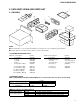
DEH-2130R,2100R 2. EXPLODED VIEWS AND PARTS LIST 2.1 PACKING 7 3 2 5 4 10 12 1 11 6 9 8 NOTE: - Parts marked by “*” are generally unavailable because they are not in our Master Spare Parts List. - Screws adjacent to ∇ mark on the product are used for disassembly. (1) PACKING SECTION PARTS LIST Mark No. Description * 1 2 3 4 5 6 7-1 7-2 7-3 7-4 Part No.
DEH-2130R,2100R 2.
DEH-2130R,2100R (1) EXTERIOR SECTION PARTS LIST Mark No. Description Part No. Mark No. Description Part No. 36 37 38 39 40 Spring Spring Spring Bracket Holder CDE6160 CEK1136 CD Mechanism Module(S8.
DEH-2130R,2100R 2.
DEH-2130R,2100R - CD MECHANISM MODULE SECTION PARTS LIST Mark No. Description Part No. Mark No. Description Part No.
2 1 3 4 DEH-2130R,2100R 3. BLOCK DIAGRAM AND SCHEMATIC DIAGRAM 3.1 BLOCK DIAGRAM A TUNER AMP ASSY A Q472 B ANTENNA Q476 Q474 FM/AM TUNER UNIT FM/AM 1ST IF 10.7MHz T51 Q51 CF51 CF52 CF53 FM FRONT END Q3 CN402 FM MPX 25 27 24 32 39 42 44 46 63 RF TV 22 Q477 6 RDS DECODER 46 VDD FM/AM 70 MIXER.
5 7 6 8 DEH-2130R,2100R A 66 61 TMUTE LDET CN301 REAR L CH 21 Q346 FM/AM SYSTEM CONTROLLER 2 6 76 10 14 13 48 12 11 67 SD SL SDBW TUNPCE TUNPCK TUNPCE2 TUNPDO VST VCK VDT TUNPDI LOCL Q353 Q903 VDD B.U B.U BACKUP FUSE 10A 2 1 2 3 VST/ VCK/ VDT IN1 ELECTRONIC VOLUME/ SOURCE SELECTOR IN2 IC 301 SN761029DL GND BACK UP GND POWER AMP Fout Rout 19 14 20 12 RL IC 302 TDA7384 FL MUTE STBY 22 4 23 FL– 21 FL+ 3 RL– 5 RL+ B.
2 1 3 4 DEH-2130R,2100R 3.2 OVERALL CONNECTION DIAGRAM(GUIDE PAGE) Note: When ordering service parts, be sure to refer to “EXPLODED VIEWS AND PARTS LIST” or “ELECTRICAL PARTS LIST”. A-a A-b A-a Large size SCH diagram A A-a A-b Guide page B FM/AM TUNER UNIT A-a A-b FM(100%):-15.5dBs AM (30%):-26dBs Detailed page CD:+4. FM(100%):-15 AM (30%):-26 123 272 DSP-201M-S00B 272 123 162 162 B 4.
5 7 6 8 DEH-2130R,2100R A-b A CD:+10.1dBs FM(100%):+6.5dBs AM (30%):-3dBs AA TUNER AMP ASSY 4.1dBs 5.5dBs 6dBs SOURCE SELECTOR/ E.VOL POWER AMP 332/16 CD:+36.1dBs FM(100%):+32.5dBs AM (30%):+23dBs CD:+10.1dBs FM(100%):+6.5dBs AM (30%):-3dBs B > CEK1136 600µH Reset D CD MECHANISM MODULE (B2) C VD REGULATOR CD:+4.1dBs 102(1/2W) D CELLULAR MUTE BACK UP B.
B FM/AM TUNER UNIT C 12 A-a 1 2 FM(100%):-15.5dBs AM (30%):-26dBs 162 123 3 B D 3 4 272 CSS1047 4.194MHz 1 2 162 SOURCE E.VOL CD:+4.1dBs FM(100%):-15.
5 6 7 The > mark found on some component parts indicates the importance of the safety factor of the part. Therefore, when replacing, be sure to use parts of identical designation. 102 *Capacitors Code Practical value 103 0.01µF 101/10 100µF/10V Ex.
A-b 1 1 D SOURCE SELECTOR/ E.VOL CD:+10.1dBs FM(100%):+6.5dBs AM (30%):-3dBs B POWER AMP 600µH A CD:+36.1dBs FM(100%):+32.5dBs AM (30%):+23dBs 2 3 C 3 4 CEK1136 2 > AA TUNER AMP ASSY 1 332/16 .1dBs 5.5dBs 6dBs CD:+10.1dBs FM(100%):+6.
2 Reset CD:+4.1dBs VD REGULATOR 5 (B2) CELLULAR MUTE 600µH 6 7 GND ACC B.
2 1 3 4 DEH-2130R,2100R 3.
5 6 7 8 DEH-2130R,2100R KV1410(23) A B C D 5 6 7 B 8 17
2 1 3 4 DEH-2130R,2100R 3.
5 7 6 8 DEH-2130R,2100R A CN601 DISP PTY A TA/AF B LOCAL/BSM C DEH-2130R/X1M/EW DEH-2100R/X1M/EW IL1801-1804 CEL1638(14V 40mA) CEL1547(14V 40mA) D 5 6 7 C 8 19
2 1 3 4 DEH-2130R,2100R 3.
5 6 7 8 DEH-2130R,2100R A SWITCHES: CONTROL UNIT S801 : HOME SWITCH.....ON-OFF S802 : CLAMP SWITCH....ON-OFF The underlined indicates the switch position.
DEH-2130R,2100R Note:1. The encircled numbers denote measuring pointes in the circuit diagram. 2. Reference voltage REFO:2.5V - Waveforms 1 RFI 0.5V/div. 0.5µs/div. Normal mode: play 1 CH1: RFI 1V/div. 0.5ms/div. 2 CH2: MIRR 5V/div. Test mode: Tracking open 1 CH1: RFI 1V/div. 0.5ms/div. 2 CH2: MIRR 5V/div. Normal mode: The defect part passes 800µm REFO → REFO → REFO → REFO → REFO → 3 CH1: FD 0.5V/div. 0.2s/div. 4 CH2: FO+ 2V/div. Test mode: No disc, Focus close 3 CH1: FD 0.5V/div. 0.2s/div.
DEH-2130R,2100R 8 CH1: TE 0.2V/div. 9 CH2: TD 0.2V/div. Normal mode: play 20ms/div. 8 CH1: TE 0.5V/div. 5ms/div. ! CH2: SD 0.5V/div. TEST mode: 100 Tracks jump(FWD) 0 MD 0.5V/div. 0.1s/div. Normal mode: Play (12cm) REFO → REFO → REFO → REFO → REFO → 0 MD 1V/div. Normal mode: Long Search (12cm) 10ms/div. @ EFM 1V/div. 5µs/div. Normal mode: play 8 CH1: TE 1V/div. 2ms/div. # CH2: TEC 1V/div. Test mode: Focus close Tracking open REFO → REFO → REFO → REFO → GND → 8 CH1: TE 0.5V/div. 0.2s/div.
DEH-2130R,2100R ( CH1: R OUT 1V/div. 0.2ms/div. ) CH2: L OUT 1V/div. Normal mode: Play (1kHz 0dB) 6 CH1: FE 0.2V/div. 1ms/div. 3 CH2: FD 0.5V/div. Normal mode: During AGC 8 CH1: TE 0.2V/div. 1ms/div. 9 CH2: TD 0.5V/div. Normal mode: During AGC REFO → REFO → REFO → REFO → REFO → REFO → 1 CH1: RFI 1V/div. 0.5ms/div. ⁄ CH2: HOLD 5V/div. Normal mode: The defect part passes 800µm(B.D) 3 CH1: FD 0.5V/div. 0.5ms/div. ⁄ CH2: HOLD 5V/div. Normal mode: The defect part passes 800µm(B.D) 9 CH1: TD 0.1V/div.
DEH-2130R,2100R 25
2 1 3 4 DEH-2130R,2100R 4. PCB CONNECTION DIAGRAM A A TUNER AMP ASSY CORD ASSY 4.1 TUNER AMP ASSY NOTE FOR PCB DIAGRAMS 1. The parts mounted on this PCB include all necessary parts for several destination. For further information for respective destinations, be sure to check with the schematic diagram. 2. Viewpoint of PCB diagrams Connector Capacitor SIDE A B P.C.
5 6 7 8 DEH-2130R,2100R A SIDE A B B C D 5 6 7 A 8 27
1 2 3 4 2 3 4 DEH-2130R,2100R A TUNER AMP ASSY A B C D 28 A 1
5 6 7 8 DEH-2130R,2100R SIDE B A B C D 5 6 7 A 8 29
2 1 3 4 DEH-2130R,2100R 4.
1 2 3 4 DEH-2130R,2100R SIDE B A B FM/AM TUNER UNIT C B D 1 2 3 B 4 31
C 1 2 1 2 3 4 5 6 TA/AF PTY LOCAL/BSM BAND AUDIO ] A - [ EJECT 4.
1 2 3 4 DEH-2130R,2100R SIDE B A A CN601 B KEYBOARD UNIT C C D 1 2 3 C 4 33
PHOTO UNIT(S8) CONTROL UNIT 1 D E 3 2 1 2 3 3 CN802 4.
1 2 3 4 DEH-2130R,2100R SIDE B A CLAMP CONTROL UNIT B D C D 1 2 3 D 4 35
DEH-2130R,2100R 5. ELECTRICAL PARTS LIST NOTES: - Parts whose parts numbers are omitted are subject to being not supplied. - The part numbers shown below indicate chip components. Chip Resistor RS1/_S___J,RS1/__S___J Chip Capacitor (except for CQS.....) CKS....., CCS....., CSZS..... =====Circuit Symbol and No.===Part Name --- ----------------------------------------------- A Part No. ------------------------- Unit Number : CWM6764 Unit Name : Tuner Amp Assy MISCELLANEOUS =====Circuit Symbol and No.
DEH-2130R,2100R =====Circuit Symbol and No.===Part Name --- ----------------------------------------------- Part No. ------------------------- =====Circuit Symbol and No.===Part Name --- ----------------------------------------------- Part No.
DEH-2130R,2100R =====Circuit Symbol and No.===Part Name --- ----------------------------------------------- Part No. ------------------------- =====Circuit Symbol and No.===Part Name --- ----------------------------------------------- Part No.
DEH-2130R,2100R =====Circuit Symbol and No.===Part Name --- ----------------------------------------------- Part No. ------------------------- =====Circuit Symbol and No.===Part Name --- ----------------------------------------------- Part No.
DEH-2130R,2100R =====Circuit Symbol and No.===Part Name --- ----------------------------------------------- D Part No. ------------------------- Unit Number : CWX2411 Unit Name : Control Unit MISCELLANEOUS IC IC IC Q D 201 301 701 101 801 IC IC IC Transistor LED UPD63711GC BA5985FM BA05SFP 2SB1132 CL200IRX D X S S 802 201 801 802 LED Ceramic Oscillator 16.934MHz Spring Switch(HOME) Spring Switch(CLAMP) CL200IRX CSS1456 CSN1051 CSN1052 Part No.
DEH-2130R,2100R 6. ADJUSTMENT 6.1 CD ADJUSTMENT 1) Precautions • This unit uses a single power supply (+5V) for the regulator. The signal reference potential, therefore, is connected to REFO(approx. 2.5V) instead of GND. If REFO and GND are connected to each other by mistake during adjustments, not only will it be impossible to measure the potential correctly, but the servo will malfunction and a severe shock will be applied to the pick-up. To avoid this, take special note of the following.
DEH-2130R,2100R - Flow Chart 4 6 Test Mode In Reset SOURCE Select CD New test mode BAND Power ON (Adjustment for T.Offset) TRK MIN Power ON (Not adjustment for T.
DEH-2130R,2100R 6.2 CHECKING THE GRATING AFTER CHANGING THE PICKUP UNIT • Note : The grating angle of the PU unit cannot be adjusted after the PU unit is changed. The PU unit in the CD mechanism module is adjusted on the production line to match the CD mechanism module and is thus the best adjusted PU unit for the CD mechanism module. Changing the PU unit is thus best considered as a last resort. However, if the PU unit must be changed, the grating should be checked using the procedure below.
DEH-2130R,2100R Grating waveform Ech → Xch 20mV/div, AC Fch → Ych 20mV/div, AC 0° 30° 45° 60° 75° 90° 44
DEH-2130R,2100R 7. GENERAL INFORMATION 7.1 DIAGNOSIS 7.1.1 TEST MODE - Error Messages If a CD is not operative or stopped during operation due to an error, the error mode is turned on and cause(s) of the error is indicated with a corresponding number. This arrangement is intended at reducing nonsense calls from the users and also for facilitating trouble analysis and repair work in servicing.
DEH-2130R,2100R - New Test Mode S-CD plays the same way as before. If an error such as off focus, spindle unlocking, unreadable sub-code, or sound skipping occurs after setup, its cause and time occurred (in absolute time) are displayed. During setup, operational status of the control software (internal RAM: CPOINT) is displayed. These displays and functions are prepared for enhancing aging in the servicing and efficiency of trouble analysis.
DEH-2130R,2100R (4) Display of Operational Status (CPOINT) during Setup Status No. Contents 01 Carriage move to home position started. 02 Carriage is moving toward inner diameter. 03 Carriage is moving toward outer diameter. 05 11 12 13 14 15 16 17 18 24 25 26 27 28 29 30 31 32 33 34 35 Carriage outer diameter feed (1 second) in progress. Setup started. Spindle rotation and focus search started. Waiting for focus close (XSI=Low). Waiting for focus close (FOK=High).
DEH-2130R,2100R 7.1.2 DISASSEMBLY - Removing the Upper Case (not shown) - Removing the CD Mechanism Module (Fig.1) Remove the four screws. Disconnect the connector and then remove the CD Mechanism Module (not shown). - Removing the Panel Assy (not shown) 1. Disconnect the two stoppers and then remove the Panel Assy. CD Mechanism Module - Removing the Tuner Amp Assy Fig.1 Cover Remove the two screws (Fig.2). Remove the three screws and then remove the Cover (Fig.2). Fig.2 Remove the screw (Fig.3).
DEH-2130R,2100R - Removing the Upper Frame 1. Remove six Springs A, two Springs B and four Screws. 2. Remove two Tabs situated on rear side of the Upper Frame, remove two Arms on the front side, then remove two Tabs on the front side. A Upper Frame A A A B A Arm Arm B A - Removing the Carriage Mechanism Carriage Mechanism Section 1.
DEH-2130R,2100R - Removing the Guide Arm Assy 1. Remove a connector, a spring A and B 2. Drive the Guide Arm Assy up aslant into rear side direction, then remove it from a Pin. Finally, drive the assembly approximately 45 degrees upward, then slide the assembly toward left side to remove it. Note : When assembling the guide arm assembly, route the cord inside the assembly. In this operation, care must be exercised so that cord may be caught by the gear.
DEH-2130R,2100R - Removing the Loading Motor and Carriage C Motor Guide 1. Remove the Spring and two Screws A. 2. Dismount the Loading Motor. 3. Remove the Belt, a Screw B, two Screws C, a Guide and a Screw Unit. 4. Dismount the Carriage Motor. Note : When assembling the Belt, use care so that it may not be contaminated by grease. B Screw Unit Carriage Motor Belt C A A Loading Motor - Removing the Pickup Unit 1. Remove two Screws and a Shaft. 2. Dismount the Pickup Unit.
DEH-2130R,2100R 7.2 PARTS 7.2.1 IC - Pin Functions(PE5090A) Pin No.
DEH-2130R,2100R Pin No.
DEH-2130R,2100R STB CLK DATA DVcc REARout-R FRNTout-R FADERin-R TONEout-R NC BASS-C2-R BASS-R-R BASS-C1-R TREB-R VRin-R LOUD-R ZCin-R SWout-R AGND IN4(-)-R IN4(+)-R IN3-R IN2-R IN1-R VCC SN761029DL 48 47 46 45 44 43 42 41 40 39 38 37 36 35 34 33 32 31 30 29 28 27 26 25 Isolator Volume, Treble Loudness Bass Fader Bass Fader Gain Adjust Power Supply A Zero-cross Detector 3 Line Serial Bus Gain Adjust Volume, Loudness Treble Power Supply PM4009A 54 ZCin-L Ct SWout-L DG
DEH-2130R,2100R BR9010FV NC VCC 1 8 WC GND CS 2 CS : Chip select input 7 SK : Serial data clock input DI : Serial data input DO : Serial data output 3 WC: Write control input 6 SK 4 DI 5 DO - Pin Functions (PD6293A) Pin No.
DEH-2130R,2100R - Pin Functions (UPD63711GC) Pin No. 1 2 3 4 5 6 7 8 9 10 11 12 13 14 15 16 17 18 19 20 21 22 23 24 25 26 27 28 56 Pin Name D.GND RFOK rst A0 stb sck SO SI xtalen D.VDD DA.VDD R_OUT DA.GND REGC DA.GND L_OUT DA.VDD R+ RLL+ X.VDD XTAL xtal X.GND D.VDD EMPH FLAG I/O O I I I I O I I O I O O O O O I O O O 29 30 31 32 33 34 DIN DOUT SCKIN SCKO LRCKIN LRCK I O I O I O 35 36 37 38 39 40 41 42 43 44 45 46 47 48 49 50 51 52 53 54 55 56 57 HOLD TX D.GND C16M LIMIT D.
DEH-2130R,2100R Pin Name TEST0 TEST1 ATEST A.GND FD TD SD MD DAC0 DAC1 DAC2 DAC3 A.VDD EFM ASY C3T RFI AGCO AGCI RFO EQ2 EQ1 RFA.GND A C B D F E A.VDD REFOUT FEFEO TETEO TE2 TEC A.GND PD LD PN A.
DEH-2130R,2100R - Pin Functions (BA5985FM) Pin No.
DEH-2130R,2100R 7.2.
DEH-2130R,2100R 7.3 OPERATIONAL FLOW CHART Power ON VDD=5V 68pin bsens 66pin L asens 65pin L dsens 63pin L ADPW←H 20pin Starts communication with Grille microcomputer. 300ms swvdd←L 41pin Source keys operative Source ON YES SYSPW←H 42pin To each source's flow chart 60 300ms In case of the above signal, the communication with Grille microcomputer may fail. If the time interval is not 300msec, the oscillator may be defective.
DEH-2130R,2100R 8. OPERATIONS AND SPECIFICATIONS 8.
Hold for 1 second 3. Turn the source OFF. 2. Raise or lower the volume. • When no disc is set in this product, built-in CD player source will not change. • When this product’s blue/white lead is connected to the car’s Auto-antenna relay control terminal, the car’s Auto-antenna extends when this product’s source is switched ON. To retract the antenna, switch the source OFF.
• The CD function can be turned ON/OFF with the disc remaining in this product. • A disc left partially inserted after ejection may incur damage or fall out. Note: Eject Continue pressing Fast Forward/Reverse • If a disc cannot be inserted fully or playback fails, make sure the recorded side is down. Push the EJECT button and check the disc for damage before reinserting it. • If a disc is inserted with the recorded side up, it will be ejected automatically after a few moments.
The display shows “+6” – “–6”. 2. Boost or attenuate the bass ∞ buttons. level with the 5/∞ 1. Press the AUDIO button and select the Bass mode (BAS) in the Audio Menu. You can adjust a Bass level as desired. Bass Adjustment (BAS) • “FAD 0” is the proper setting when 2 speakers are in use. Note: “BAL L9” – “BAL R9” is displayed as it moves from left to right. 3. Adjust left/right speaker bal3 buttons. ance with the 2/3 “FAD F15” – “FAD R15” is displayed as it moves from front to rear. 2.
4* 5* 3. Antenna jack 1. This product 14. Speaker leads White : Front left + White/black : Front left ≠ Gray : Front right + Gray/black : Front right ≠ Green : Rear left + Green/black : Rear left ≠ Violet : Rear right + Violet/black : Rear right ≠ 11. Red (4*) To electric terminal controlled by ignition switch (12 V DC) ON/OFF. 10. Red (5*) Accessory (or back-up) 12. Black (ground) To vehicle (metal) body. 9. Yellow (2*) To terminal always supplied with power regardless of ignition switch position.
DEH-2130R,2100R 8.2 SPECIFICATIONS General FM tuner Power source .......... 14.4 V DC (10.8 – 15.1 V allowable) Grounding system ........................................ Negative type Max. current consumption ...................................... 10.0 A Dimensions (mounting size) ...... 178 (W) × 50 (H) × 159 (D) mm (front face) .............. 188 (W) × 58 (H) × 19 (D) mm Weight ...................................................................... 1.4 kg Frequency range ..............................