OB387-1.qxp 05.2.21 10:03 AM Page 1 SPLIT-TYPE, HEAT PUMP AIR CONDITIONERS HFC No. OB387 utilized SERVICE MANUAL R410A Wireless type Models MUH-GA20VB MUH-GA25VB MUH-GA35VB - E1 E1 E1 CONTENTS Indication of model name MUH-GA20VB MUH-GA25VB MUH-GA35VB - E1 E1 E1 1. TECHNICAL CHANGES ····································2 2. PART NAMES AND FUNCTIONS······················6 3. SPECIFICATION·················································6 4.
OB387-1.qxp 1 05.2.21 10:03 AM Page 2 TECHNICAL CHANGES MUH-A07YV- E1 ➔MUH-GA20VB- E1 1. 2. 3. 4. 5. 6. 7. Indication of capacity has been changed. (BTU base ➔ kw) Dimension of outdoor unit has been changed. (780Wo540Ho255D ➔ 800Wo550Ho285D) Stop valve cover has been added. Outdoor fan motor has been changed. (RC6V20-AB ➔ RA6V21-AD) Outdoor fan motor capacitor has been changed. Compressor capacitor has been changed. Outdoor heat exchanger has been changed.
05.2.21 10:03 AM Page 3 INFORMATION FOR THE AIR CONDITIONER WITH R410A REFRIGERANT • This room air conditioner adopts HFC refrigerant (R410A) which never destroys the ozone layer. • Pay particular attention to the following points, though the basic installation procedure is same as that for R22 conditioners. 1 As R410A has working pressure approximate 1.6 times as high as that of R22, some special tools and piping parts/ materials are required. Refer to the table below.
OB387-1.qxp 05.2.21 10:03 AM Page 4 Conversion chart of refrigerant temperature and pressure (MPa [Gauge]) 4.0 Saturated liquid pressure 3.5 R410A 3.0 R22 2.5 2.0 NOTE : The unit of pressure has been changed to MPa on the international system of units(SI unit system). 1.5 1.0 f [Gauge]) The conversion factor is: 1(MPa [Gauge]) =10.2(kgf/f 0.5 0.0 -0.5 -30 -20 -10 0 10 20 30 40 50 60 (:) 1.
OB387-1.qxp 05.2.21 10:03 AM Page 5 2 Flaring work and flare nut Flaring work for R410A pipe differs from that for R22 pipe. For details of flaring work, refer to Installation manual “FLARING WORK”. Dimension of flare nut Pipe diameter mm R410A R22 6.35 17 17 9.52 22 22 3.Refrigeration oil Apply the special refrigeration oil (accessories: packed with indoor unit) to the flare and the union seat surfaces. 4.Air purge • Do not discharge the refrigerant into the atmosphere.
OB387-1.qxp 2 05.2.
05.2.21 10:03 AM Page 7 NOISE CRITERIA CURVES 4 MUH-GA20VB- E1 FUNCTION SPL(dB(A)) MUH-GA25VBMUH-GA35VB- LINE COOLING HEATING 47 Test conditions, Cooling :DB35: Heating :DB 7: 90 FUNCTION COOLING E1 SPL(dB(A)) LINE 49 HEATING Test conditions, Cooling :DB35: Heating :DB 7: WB24: WB 6: 90 80 70 NC-70 60 NC-60 50 NC-50 40 NC-40 30 NC-30 20 E1 WB24: WB 6: OCTAVE BAND SOUND PRESSURE LEVEL, dB re 0.0002 MICRO BAR OCTAVE BAND SOUND PRESSURE LEVEL, dB re 0.0002 MICRO BAR OB387-1.
OB387-1.qxp 05.2.21 10:03 AM 5 Page 8 OUTLINES AND DIMENSIONS MUH-GA20VB - E1 MUH-GA25VB - E1 MUH-GA35VB - E1 Unit: mm OUTDOOR UNIT REQUIRED SPACE Basically open 100mm or more without any obstruction in front and on both sides of the unit. ore mm or m or m Bolt pitch for installation 304~325 ore 44 Air in (MUH-GA25 /GA35VB) 40 2 holes 10X21 ore rm mo 00m 2 Open two sides of left, right, or rear side. 17.5 Service panel Air out 23 22.
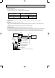
05.2.21 10:03 AM WIRING DIAGRAM MUH-GA20VB - E1 OUTDOOR UNIT MUH-GA25VB - E1 MUH-GA35VB - E1 MODELS WIRING DIAGRAM 21S4 3 2 1 CN730 RED BLK CN661 CN721 BRN F61 TB1 L NR61 N CIRCUIT BREAKER SR61 T61 BLU N TAB20 52C BRN PE 4 GRN/YLW CN711 SR62 TB2 3 DSAR TO INDOOR UNIT CONNECTING 12V RT61 C65 3 2 1 6 Page 9 POWER SUPPLY ~/N 230V 50Hz OB387-1.
OB387-1.qxp 7 05.2.21 10:03 AM Page 10 REFRIGERANT SYSTEM DIAGRAM MUH-GA20VB - E1 MUH-GA25VB - E1 Unit:mm MUH-GA35VB - E1 OUTDOOR UNIT Refrigerant pipe [ 9.52 (with heat insulator) Flared connection 4-way valve Stop valve (with service port) Muffler Flared connection Strainer #100 Defrost thermistor RT61 Compressor Capillary tube [3.0x[1.4x700 (MUH-GA20VB) [3.0x[1.4x1000(MUH-GA25VB) [3.0x[1.4x500 (MUH-GA35VB) Check valve Outdoor heat exchanger R.V.
OB387-1.qxp 05.2.21 10:03 AM Page 11 MAX. REFRIGERANT PIPING LENGTH Refrigerant piping Piping size O.D : mm Max. length : m Model A MUH-GA20VB - E1 MUH-GA25VB - E1 MUH-GA35VB - Gas Liquid 9.52 6.35 Length of connecting pipe : m Indoor unit Outdoor unit Gas 0.43 Gas 0 Liquid 0.5 Liquid 0 20 25 E1 MAX. HEIGHT DIFFERENCE Indoor unit Height difference should be within 10m regardless of which unit, indoor or outdoor position is high. Refrigerant Piping Max.length A w Max.
OB387-1.qxp 05.2.21 10:03 AM Page 12 How to measure the indoor air wet-bulb/dry-bulb temperature difference 1. 2. 3. 4. 5. 6. 7. Attach at least 2 sets of wet-and dry-bulb thermometers to the indoor air intake as shown in the figure, and at least 2 sets of wet-and dry-bulb thermometers to the indoor air outlet. The thermometers must be attached to the position where air speed is high. Attach at least 2 sets of wet-and dry-bulb thermometers to the outdoor air intake.
OB387-1.qxp 05.2.21 10:03 AM Page 13 8-2.OUTDOOR LOW PRESSURE AND OUTDOOR UNIT CURRENT COOL operation ➁ ③ Both indoor and outdoor unit are under the same temperature/humidity condition. Dry-bulb temperature Relative humidity(%) 20 50 25 60 30 70 Air flow should be set at MAX. The unit of pressure has been changed to MPa on the international system of units(SI unit system). f[Gauge] ) The conversion factor is : 1(MPa[Gauge]) =10.2(kgf/f Outdoor low pressure (kgf/F[Gauge])(MPa[Gauge]) 13 1.
OB387-1.qxp 05.2.21 10:03 AM Page 14 HEAT operation Outdoor:Dry bulb temperature 7,15,20°C Wet bulb temperature 6,12,14.5°C Condition indoor:Dry bulb temperature 20.0°C Wet bulb temperature 14.
OB387-1.qxp 05.2.21 10:03 AM Page 15 PERFORMANCE DATA COOL operation (230V) MSC-GA20VB - E1 : MUH-GA20VB - E1 CAPACITY : 2.3(kW) SHF : 0.74 INDOOR INDOOR DB(:) WB(:) 21 18 21 20 22 18 22 20 22 22 23 18 23 20 23 22 24 18 24 20 24 22 24 24 25 18 25 20 25 22 25 24 26 18 26 20 26 22 26 24 26 26 27 18 27 20 27 22 27 24 27 26 28 18 28 20 28 22 28 24 28 26 29 18 29 20 29 22 29 24 29 26 30 18 30 20 30 22 30 24 30 26 31 18 31 20 31 22 31 24 31 26 32 18 32 20 32 22 32 24 32 26 NOTE Q 2.70 2.82 2.70 2.82 2.
OB387-1.qxp 05.2.21 10:03 AM Page 16 PERFORMANCE DATA COOL operation (230V) MSC-GA20VB - E1 : MUH-GA20VB - E1 CAPACITY : 2.3(kW) SHF : 0.74 INPUT : 715(W) OUTDOOR DB(:) 35 40 INDOOR INDOOR DB(:) WB(:) Q SHC SHF INPUT Q SHC SHF INPUT Q 21 18 2.25 1.26 0.56 701 2.07 1.16 0.56 744 1.99 21 20 2.37 1.04 0.44 729 2.21 0.97 0.44 765 2.13 22 18 2.25 1.35 0.60 701 2.07 1.24 0.60 744 1.99 22 20 2.37 1.14 0.48 729 2.21 1.06 0.48 765 2.13 22 22 2.51 0.90 0.36 758 2.35 0.84 0.36 801 2.27 23 18 2.25 1.44 0.
OB387-1.qxp 05.2.21 10:03 AM Page 17 PERFORMANCE DATA COOL operation (230V) MSC-GA25VB - E1 : MUH-GA25VB - E1 CAPACITY : 2.65(kW) SHF : 0.70 INPUT : 820(W) OUTDOOR DB(:) 21 25 27 INDOOR INDOOR DB(:) WB(:) Q SHC SHF INPUT Q SHC SHF INPUT Q SHC SHF INPUT Q 21 18 3.11 1.62 0.52 656 2.98 1.55 0.52 689 2.86 1.49 0.52 722 2.76 21 20 3.25 1.30 0.40 689 3.11 1.25 0.40 730 3.02 1.21 0.40 746 2.92 22 18 3.11 1.74 0.56 656 2.98 1.67 0.56 689 2.86 1.60 0.56 722 2.76 22 20 3.25 1.43 0.44 689 3.11 1.37 0.
OB387-1.qxp 05.2.21 10:03 AM Page 18 PERFORMANCE DATA COOL operation (230V) MSC-GA25VB - E1 : MUH-GA25VB - E1 CAPACITY : 2.65(kW) SHF : 0.70 INDOOR INDOOR DB(:) WB(:) 21 21 22 22 22 23 23 23 24 24 24 24 25 25 25 25 26 26 26 26 26 27 27 27 27 27 28 28 28 28 28 29 29 29 29 29 30 30 30 30 30 31 31 31 31 31 32 32 32 32 32 NOTE Q INPUT : 820(W) OUTDOOR DB(:) 35 40 SHC SHF INPUT Q SHC SHF INPUT 18 2.60 1.35 0.52 804 20 2.73 1.09 0.40 836 18 2.60 1.45 0.56 804 20 2.73 1.20 0.44 836 22 2.89 0.92 0.
OB387-1.qxp 05.2.21 10:03 AM Page 19 PERFORMANCE DATA COOL operation (230V) MSC-GA35VB - E1 : MUH-GA35VB - E1 CAPACITY : 3.5(kW) SHF : 0.66 INDOOR INDOOR DB(:) WB(:) 21 18 21 20 22 18 22 20 22 22 23 18 23 20 23 22 24 18 24 20 24 22 24 24 25 18 25 20 25 22 25 24 26 18 26 20 26 22 26 24 26 26 27 18 27 20 27 22 27 24 27 26 28 18 28 20 28 22 28 24 28 26 29 18 29 20 29 22 29 24 29 26 30 18 30 20 30 22 30 24 30 26 31 18 31 20 31 22 31 24 31 26 32 18 32 20 32 22 32 24 32 26 NOTE Q 4.11 4.29 4.11 4.29 4.
OB387-1.qxp 05.2.21 10:03 AM Page 20 PERFORMANCE DATA COOL operation (230V) MSC-GA35VB - E1 : MUH-GA35VB - E1 CAPACITY : 3.5(kW) SHF : 0.66 INPUT : 1090(W) OUTDOOR DB(:) 35 40 INDOOR INDOOR DB(:) WB(:) Q SHC SHF INPUT Q SHC SHF INPUT Q 21 18 3.43 1.65 0.48 1068 3.15 1.51 0.48 1134 3.03 21 20 3.61 1.30 0.36 1112 3.36 1.21 0.36 1166 3.24 22 18 3.43 1.78 0.52 1068 3.15 1.64 0.52 1134 3.03 22 20 3.61 1.44 0.40 1112 3.36 1.34 0.40 1166 3.24 22 22 3.82 1.07 0.28 1155 3.57 1.00 0.28 1221 3.45 23 18 3.43 1.
OB387-1.qxp 05.2.21 10:03 AM Page 21 PERFORMANCE DATA HEAT operation (230V) MSC-GA20VB - E1 : MUH-GA20VB - E1 CAPACITY : 2.5(kW) INPUT : 690(W) OUTDOOR WB(:) INDOOR -10 -5 0 5 10 15 20 DB(:) Q INPUT Q INPUT Q INPUT Q INPUT Q INPUT Q INPUT Q INPUT 3.50 731 2.88 697 3.18 718 2.23 607 2.55 656 1.58 449 1.90 538 15 3.36 766 2.75 718 3.05 738 2.13 635 2.43 683 1.50 483 1.80 573 21 3.25 794 2.63 752 2.93 773 1.98 669 2.30 718 1.35 518 1.68 607 26 MSC-GA25VB - E1 CAPACITY : 3.
OB387-1.qxp 9 05.2.21 10:03 AM Page 22 SERVICE FUNCTIONS MUH-GA20VB - E1 MUH-GA25VB - E1 MUH-GA35VB - E1 9-1. COMPULSORY DEFROSTING MODE FOR SERVICE By short circuit of the connector JPDS and JPSG on the outdoor deicer P.C. board, defrosting mode can be accomplished regardless of the defrost interval restriction. (Refer to 10-5.) Defrost thermistor RT61 must read below -3°C. 9-2. CHANGE IN DEFROST SETTING When the JRF wire of the deicer P.C.
OB387-1.qxp 05.2.21 10:03 AM Page 23 10-2. Instruction of troubleshooting MUH-GA20VB - E1 MUH-GA25VB - E1 MUH-GA35VB - E1 Start Indoor unit operates. Outdoor unit doesn't operate normally. Indoor unit operates. Outdoor unit doesn't operate. Outdoor unit operates in only Test Run operation. Check room temperature thermistor. Refer to 10-5 "Test point diagram and voltage". Outdoor unit doesn't operate even in Test Run operation. Refer to 10-4. A "Check of outdoor unit".
OB387-1.qxp 05.2.21 10:03 AM Page 24 10-3. Trouble criterion of main parts MUH-GA20VB - E1 MUH-GA25VB - E1 MUH-GA35VB - E1 Figure Check method and criterion Part name Measure the resistance with a tester. (Part temperature –10°C ~ 40°C) Defrost thermistor (RT63) Compressor (MC) INNER PROTECTOR Normal Abnormal 5kΩ ~ 60kΩ Open or short-circuit Measure the resistance between the terminals with a tester.
OB387-1.qxp 05.2.21 10:03 AM Page 25 Compressor and/or outdoor fan motor doesn’t stop. B Check of outdoor unit Start Turn OFF the power supply. After 1 minute, turn ON power supply again. No Does compressor stop? Yes OK No Rectify the connecting wire. Replace the deicer P.C. board. No Does outdoor fan motor stop? Is there 230V AC between 3 on the compressor contactor (52C) and N on the outdoor terminal block (TB1)? Yes Replace the deicer P.C. board.
OB387-1.qxp 05.2.21 10:03 AM Page 26 When OPERATION INDICATOR lamp flashes 0.5-second intervals or 1-time. Outdoor unit does not operate. D How to check mis-wiring and serial signal error w 1 Set the switch(SW2-2) on indoor electronic control P.C. board to MU or MUX type, when the outdoor unit is MU or MUX type. If the setting is MUH or MXZ type, the unit does not work. Start w 2 Short circuit of JPG and JPS on the indoor electronic control P.C. board enables self-check to be displayed in 3 seconds.
OB387-1.qxp 05.2.21 10:03 AM Page 27 When OPERATION INDICATOR lamp flashes 6-time. Thermistors in the outdoor unit are abnormal. E Check of outdoor thermistor Start Replace the deicer P.C. board. Defrost thermistor (RT61) Turn OFF the power supply. Measure resistance between CN 661 1 and 2. Is the resistance of thermistor normal? Yes No Reconnect CN661. Turn ON the power supply and press the EMERGENCY OPERATION switch.
OB387-1.qxp 05.2.21 10:03 AM Page 28 10-5. Test point diagram and voltage Power supply input 230V AC } } CN711 CN721 Outdoor fan motor R.V. coil 230V AC 230V AC } MUH-GA20VB - E1 MUH-GA25VB - E1 MUH-GA35VB - E1 Outdoor deicer P.C. board NR61 Varistor F61 Fuse 2A/250V + -- } 5V DC J205 + J101 -12V DC J204 + J101 -- 28 R601 5~10VDC Defrost interval time short pin (JPDS, JPSG) (Refer to 9-1.) Jumper wire for change in defrost setting (JRF,JRG) (Refer to 9-2.
OB387-2.qxp 05.2.21 10:03 AM 11 Page 29 DISASSEMBLY INSTRUCTIONS <"Terminal with locking mechanism" Detaching points> The terminal which has the locking mechanism can be detached as shown below. There are two types ( Refer to (1) and (2)) of the terminal with locking mechanism. The terminal without locking mechanism can be detached by pulling it out. Check the shape of the terminal before detaching. (1) Slide the sleeve and check if there is a locking lever or not.
OB387-2.qxp 05.2.21 10:03 AM Page 30 OPERATING PROCEDURE PHOTOS 2. Removing the deicer P.C. board Photo 4 (1) Remove the service panel and the cabinet. (2) Disconnect all the connectors and the terminals on the deicer P.C. board. (3) Remove the deicer P.C. board. Screw of the Deicer relay panel P.C. board Relay panel Terminal block Surge absorber 3. Removing the propeller and the outdoor fan motor (1) Remove the cabinet. (Refer to 1.) (2) Remove the propeller nut. (3) Remove the propeller.
OB387-2.qxp 05.2.21 10:03 AM Page 31 OPERATING PROCEDURE PHOTOS 4. Removing the compressor (1) (2) (3) (4) (5) Remove the cabinet. (Refer to 1.) Remove the relay panel. Remove the soundproof felt. Remove the terminal cover on the compressor. Disconnect lead wires from the glass terminal of the compressor. (6) Recover gas from the refrigerant circuit. NOTE : Recover gas from the pipes until the pressure gauge shows 0 kg/cm2 (0 MPa). (7) Disconnect the welded part of the discharge pipe.
OB387-2.qxp 12 05.2.21 10:03 AM Page 32 PARTS LIST MUH-GA20VB - E1 MUH-GA25VB - E1 MUH-GA35VB - E1 12-1. OUTDOOR UNIT STRUCTURAL PARTS 22 21 20 19 18 17 16 15 14 1(W) 2 24 23 3 13 4 5 6 7 8 9 10 11 12 (W) This figure shows MUH-GA20VB.
OB387-2.qxp 05.2.21 10:03 AM Page 33 MUH-GA20VB - E1 MUH-GA25VB - E1 MUH-GA35VB - E1 12-1. OUTDOOR UNIT STRUCTURAL PARTS Part numbers that are circled are not shown in the illustration. No. 1 2 3 4 5 6 7 8 9 10 11 12 13 14 15 16 17 18 19 20 21 22 23 24 25 26 27 28 29 30 31 32 33 Part No.
OB387-2.qxp 05.2.
OB387-2.qxp 05.2.
OB387-2.qxp 05.2.21 10:03 AM Page 36 HEAD OFFICE: MITSUBISHI DENKI BLDG.,2-2-3, MARUNOUCHI, CHIYODA-KU, TOKYO100-8310, JAPAN C Copyright 2005 MITSUBISHI ELECTRIC ENGINEERING CO.,LTD Distributed in Feb. 2005. No.OB387 6 Made in Japan New publication, effective Feb. 2005 Specifications subject to change without notice.