TECHNICAL MANUAL (Ver.2.0) MULTI PROJECTION UNIT RM-V4000V/ V5000V PROJECTION SCREEN KIT RMS-V4011/ V5011 PROJECTION FRAME RMF-V4011/ V5011 PROJECTION CABINET RMF-V4011R Caution This symbol refers to a hazard or unsafe practice which can result in personal injury or property damage. Notes: • Pioneer will not be liable for any loss caused by defects of the parts supplied other than by Pioneer.
PIONEER RM-V4000 / 5000 MANUAL. This Acrobat (IE: a PDF file) version of the Pioneer RM-V4000 / 5000 manual was made from the original digital document and scanning an existing manual. Because of this, there are many less then perfect pages and hand written comments. As Pioneer is constantly working towards providing the best possible documentation for our products, there may be an improved version of this document available. Please contact your Pioneer representative for additional information.
CONTENTS CHAPTER 1. FEATURES OF PROJECTION CUBE SYSTEM .............................................................. 4 1. FEATURES OF SYSTEM ........................................................................................................................................... 4 2. FEATURES OF MULTI PROJECTION UNIT (RM-V4000V/V5000V) ........................................................................ 4 3. FEATURES OF FRAME TYPE .......................................................................
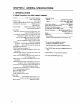
GENERAL SPECIFICATIONS Dimensions (Fig.
GENERAL SPECIFICATIONS No.
GENERAL SPECIFICATIONS (2) Projection Screen Kit (RMS-V4011/V5011) Product Weight : 11.0 kg/14.0kg 845 148 (1031) (148) 630 (769) (Fig.2-2) Unit:mm The number in parentheses is the dimentsion for RMS-V5011 Accessory Screw rivet ...........................................................................................................................
GENERAL SPECIFICATIONS (3) Projection Frame (RMF-V4011/V5011) Product Weight : 26.8kg/28.8kg 1201(1352) (769) 630 845(1031) (Fig.2-3) Unit:mm The number in parentheses is the dimension for RMS-V5011 Accessories Metal fixture (R) ................................................................................................................... 1 Metal fixture (L) .................................................................................................................... 1 Stopper ..............
GENERAL SPECIFICATIONS (7) Multi Video Processor (RMD-V3216/V3109, RMD-V2170) 1 Multi Video Processor (RMD-V3216/V3109) Rear View 0 0 299 15 430 D 314 POWER ON OFF MULTI VIDEO PROCESSOR RMD-V3216 16 19 420 482.6 Side View Front View (Fig.2-7) Main Specifications of Multi Video Processor (RMD-V3216/V3109) Input signal Input video signal (Can be expanded up to four systems) 2-line (RMD-V3216), 1-line (RMD-V3109) ... BNC terminal 1 Composite video signal .......................................
GENERAL SPECIFICATIONS 2 Multi Video Processor (RMD-V2170) Front View Side View Rear View (Fig.2-8) Main Specifications of Multi Video Processor (RMD-V2170) Input video signal ..........................................NTSC format Input signal band ...................................... Above 4.2 MHz Input Video input Input signal ............................................................... ...................... NTSC composite video signal (BNC) Input system .......................................
GENERAL SPECIFICATIONS (7) Adjustment Control Unit (RU-V107)*Option 84 DÎ ADJUSTMENT CONTROL UNIT RU-V107 0 ADJ IN 1 2 3 4 5 6 7 8 9 A D B E C F ADJ R ON/OFF G ADJ ON/OFF 187 POWER ADJ B ON/OFF INPUT SEL MAIN MENU 2 /– +/3 DISP CALL ADJ OUT 29 (Fig.2-9) Accessories AA dry battery (IEC R6P) ..................................................................................................... 2 Cable (5m) .........................................................................
GENERAL SPECIFICATIONS (8) Projection Cabinet (RMF-V4011R) Accessories To attach the multi-projection unit (RM-V4000V) to the conventional RM-V2000A, the RMF-V4011R accessories (metal fixtures) are required. The following lists the required parts. For details of attaching the multi-projection unit, refer to Chapter 3. "4(2)Assembling the System". Frame R (BNG1207) ...................................................................................................... 1 Frame L (BNG1208) ....................
CHAPTER 3. INSTALLATION AND ASSEMBLY 1. INSTALLATION CONDITIONS (1) Installing Ground 1 Ground The ground must be flat and horizontal. It should be able to bear the weight of the system. For wooden floors, if the part receiving the weight of the system lies at the center between the reinforcement beams below the floor, the floor may become deformed or may curve inwards. In such cases, lay a more than 12 mm thick board below the system to distribute the weight of the system on the floor.
INSTALLATION AND ASSEMBLY (11) Lighting • The projection screen kit (RMS-V4011/V5011) will not reflect like TV screens when exposed to external light, but may reflect if directly exposed to strong lights such as spotlight. Therefore, make sure that the screens are not exposed to direct spotlight. • For certain installation location conditions, a glass sheet may have to be attached to the screen surface. In this case, as there will be reflection by external light, consider the installation position, etc.
INSTALLATION AND ASSEMBLY 2. INSTALLATION AND ASSEMBLY (1) Confirmation 1 Decide the position for installing the system according to the installation conditions in Chapter 3. Check Items [1] Dimensions of installing position, space at the back, distance to the ceiling [2] Floor flatness, strength, roughness [3] Position of power supply [4] Installing location Necessity ti strengthen the floor, wall, etc.(reinforcement cover, sheet, plank, etc.
INSTALLATION AND ASSEMBLY 3 Multi Projection Unit (RM-V4000V/V5000V) [1] Open the upper carton, and remove the ABL cable and instruction manual provided. [2] Remove the upper carton (the pad will be connected to the upper carton). [3] Remove the upper pad. [4] Take out the unit (must be taken out by two persons). [1] [2] [3] [4] (Fig.
INSTALLATION AND ASSEMBLY 4 Projection Screen Kit (RMS-V4011/V5011) * Projection screen kit is double-packaged to maintain its performance. After removing the middle cover protecting its screen, make sure the screen does not get scratched or dirty. [1] Remove the top cover. [2] Remove the band securing the middle cover and remove the middle cover. [3] Gently peel off the black tape pasted at the four sides of the screen. Be careful not to damage the lenticular sheet.
INSTALLATION AND ASSEMBLY 5 Projection Frame (RMF-V4011/V5011) [1] Open the upper carton and cut the PP bands (eight) securing the internal parts. [2] Remove the two horizontal frame assemblies (packaged in a card box), fixtures (R) and (L). [3] Remove the H-shape frame assembly (L). [4] Remove the base assembly. [5] Remove the H-shape frame assembly (R). [6] Remove the shield attached to the under carton, bag containing accessories, and instruction manual.
INSTALLATION AND ASSEMBLY 6 Projection Cabinet (RMF-V4011R) [1] Open the upper carton and remove packings B and C, and the instruction manual. [2] Remove the upper carton. [3] Remove the top sheet B and peel off the front and back sheets B. [4] Remove the cabinet. (Hold the handle of the cabinet by two persons.) [5] Remove sheet B. [6] Remove the parts from the under carton. (Fig.
INSTALLATION AND ASSEMBLY (3) Carrying the Units After Opening Packaging To carry the screen unit and multi-projection unit after opening the packaging, hold them by the parts shown in the figure, and lift and move them. Screen Unit (Lifted by one or two persons) Multi-Projection Unit (Must be lifted by two persons) Hold the parts indicated by (Fig. 3-11) • Never drag the system along the floor when moving the units. • The lenticular sheet damages very easily as it is very thin.
INSTALLATION AND ASSEMBLY 4. ASSEMBLING THE SYSTEM (1) Assembling the Projection Frame (RMF-V4011/V5011) Assemble the projection frame as follows. [1] Mount the stopper onto the base assembly and tighten the screws (M5 × 35). (2 × 2 points) [2] Mount the H-shape frame assemblies (R) and (L), and tighten the screws (M5 × 10). (4 × 4 points) [3] Mount the horizontal frame assemblies (two) and tighten the screws (M5 × 10).
INSTALLATION AND ASSEMBLY (2) Assembling the System The basic procedure for assembling the system is as follows. 1 Assemble the projection stand (RM-V112/RMA-V5010). 2 Mount a one-link mount unit . (40-inch only) 3 4 5 6 Assemble the projection frame (RMF-V4011/V5011). Mount the multi-projection unit (RM-V4000V/V5000V). Mount the projection screen kit (RMS-V4011/V5011). Mount the top board , side board , rear panel. The basic procedure for assembling the system for rental-use is as follows.
INSTALLATION AND ASSEMBLY 4 Multi Projection Unit (RM-V4000V/V5000V) The Multi-Projection Unit is designed to be mounted from the back of the cabinet normally. If sufficient space cannot be left at the back, it can be mounted from the front. Mount from front Mount from back (Fig.3-18) a When mounting from the back [1] Pull the table of the cabinet to the back. (Fig. 3-19) [2] Insert the (M5 × 35) into the holes (Fig. 3-20) on the table. (To prevent the table from moving when placing the projection unit.
INSTALLATION AND ASSEMBLY b When mounting from the front [1] Remove the two stoppers and two metal fixtures from the cabinet. (Fig. 3-23) [2] Pull the table to the front. [3] Insert the screws (M5 × 35) into the holes on the table. [4] Place the multi-projection unit on the table. [5] Attach the metal fixtures to the table. [6] Decide the position of the multi-projection unit and attach it to the metal fixture with the four (M5 × 10). (Fig.
INSTALLATION AND ASSEMBLY 5 Projection Screen Kit (RMS-V4011/V5011) [1] Mount the screen unit serving as the reference. Basically, mount from the center unit at the bottom. a If the number of units arranged are odd (E.g.: 3 × 3=9 screens) • Adjust the screen unit to the cabinet at the center of the bottom level and temporarily tighten the linking bolts. (Do not tighten tightly.) • Adjust the left and right balance with your hand and tighten the linking bolts tightly so that the two centers coincide.
INSTALLATION AND ASSEMBLY [2] Join the next screen beside the screen mounted as the reference and mount the remaining screens in order. (Stack them from the bottom to the top.) [3] If necessary, attach the screw rivet (BEC1082) provided as the accessory of RMS-V4011. (Fig. 3-27) (Fig. 3-27) * This part is used to shield the light leaking from the big hole (ø 8) on the outermost side of the left and bottom projection units (diagonally shaded part in Fig. 3-28) after installing the system.
INSTALLATION AND ASSEMBLY 6 Top panel, Side panel, Rear panel As this system is of the rear projection type, it must be enclosed to avoid exposure to external light. (Fig.3-29) Side panel Top panel Side panel (Fig.
INSTALLATION AND ASSEMBLY 3' Attaching the Multi Projection Unit (RM-V4000V) to the Projection Cabinet (RMFV4011R) The figure shows the assembling procedure of the left attachment. Assemble the right attachment in the same way. The parts on the right side of the screen are R and those on the left side are L from the view point against the screen. (1) Attach the attachments R and L (BNG1173, 1174) to the front of frames R and L (BNG1207, 1208) using the screw (M5 ×15).
INSTALLATION AND ASSEMBLY (5) Paste spacer A (BMR1073) to the top board of the multi-projection1234 unit and spacers B (BMR1074) to the two sides at the1234 1234 position shown in the figure after peeling off the seal. (7) Attach the attachments R and L to the unit through the top board of the unit using the screws (M6 × 20) and then attach attachments R and L to the unit from the back using screws (M6 × 20). (2 screws × 2 locations).
INSTALLATION AND ASSEMBLY (10) Attach the adjuster (BEF1011) attached with a nut (M8) to the rear holders R and L (BNG1205 and 1206). (11) While tilting the parts assembled at step 10, insert it into the holes on the shoulder of the multi-projection unit and attach with the screws (3 × 12). (2 screws × 2 locations). Furthermore, pull up the adjuster to the top of the unit while rotating it, and pull down the nut to the rear holders R and L while rotating it to secure the projection unit.
INSTALLATION AND ASSEMBLY 5. SPECIAL INSTALLATION (1) Wall inset • If removing the screen after installing the system, the person must go behind the screen (diagonally shaded part of the figure). Therefore when insetting the unit in the wall, careful take this into account before installation. Screen • When fixing the screen into the wall, space for placing your hand inside the wall at the top, bottom, right, and left will be required in addition to the above in order to attach and remove the screen.
CHAPTER 4. ADJUSTMENTS 1. ADJUSTMENT PREPARATIONS (1) Wiring 1 Connection of Power Supply • The power supply can be connected to up to 3 units in a series using the AC outlets of Multi projection units. Connect the three units as one system to the external outlet. • The AC plug of Multi projection unit is a 3P with a ground pin. When connecting it to a normal outlet, use an exclusive 3P AC adapter. • The AC plug of Multi projection unit is a 3P with a ground pin.
ADJUSTMENTS When TV SYSTEM=AUTO • Automatically selects the convergence memory as follows. For NTSC input:MEMORY 1 For PAL input:MEMORY 2 Horizontal frequency 20 kHz to 28 kHz input:MEMORY 3 Horizontal frequency 28 kHz to 35 kHz input :MEMORY 4 When TV SYSTEM=NTSC • The convergence memory is always set to MEMORY 1 regardless of the input signal.
ADJUSTMENTS (3) White Balance Adjustment Memory ADJUSTMENTS has altogether six white balance adjustment memories. Color mode 1 (Normal) VIDEO, Y/C input memory RGB input memory Factory shipment memory Color mode 2 (Re-expose) VIDEO, Y/C input memory RGB input memory Factory shipment memory Four memories can be actually adjusted except the factory shipment memory. The factory shipment memory contains the normal white balance adjustment data and re-expose white balance adjustment data.
ADJUSTMENTS (6) Giving IDs When several Multi projection units are used to compose the 9 screens or 16 screens (multi-screen), the ID is used to differentiate between Multi projection units. When the units are given IDs, by connecting the ABL link cable, commands can be transmitted by specifying the ID, and it is possible to operate only Multi projection unit corresponding to that ID by remote control operations.
ADJUSTMENTS [1] Enter the adjustment mode. [2] 1 The main menu will be displayed. Press the key. Select ”1. ID CLEAR/SET/SELECT” [3] Check that the ID display at the top left of the screen is “– –” and press the 1 key. Select “1.ID SET”. If an ID has already been given, press the 0 key, select “0. ID CLEAR” of the main menu, return to “[1] Enter the adjustment mode.” and give the ID.
ADJUSTMENTS 3.
ADJUSTMENTS (3) When Switching Source Inputs to Multi Video Processor (1)When using Pioneer's new Multi Video Processor NTSC Personal Computer 1 Multi Video Processor Expanded NTSC RGB Cube Expanded Personal Computer 2 Input Function) RGB TV SYSTEM) AUTO Converter data required for display) One *The phase difference of each input source can be adjusted at the Multi Video Processor side. *When switching between the same NTSC, it is needed to switch by CUBE side.
ADJUSTMENTS (5) When Using Two Multi Video Processors without Frame Adjusting Function Multi Video Processor 1 Multi Video Processor 2 Input Function) TV SYSTEM) NTSC Expanded Cube RGB PAL Expanded RGB AUTO (Or synchronize with the switching of Multi Video Processor 1/2 and switch NTSC fixing/PAL fixing) The converter data required for display) Two * MEMORY1/2 is automatically switched by the microprocessor (6) When Single Screen is Used VGA Cube RGB MAC Input Function) RGB TV SYSTEM) AUTO Conve
ADJUSTMENTS (7) When Switching the Source Input to the Multi Video Processor NTSC Personal Computer 1 Personal Computer 2 Expanded NTSC ƒH=31.75 kHz ƒH=31.75 kHz Multi Video Processor RGB ƒH=35 kHz Cube ƒH=35 kHz Input Function: TV SYSTEM: RGB AUTO Converter data required for playing: Three For example, set as follows, and switch the data to input using RS-232C.
ADJUSTMENTS 4. SCREEN ADJUSTMENTS (1) Adjustment Flowchart The following shows the order for performing the adjustments generally required in the setup of the multi-projection system. For details, see the descriptions on the next page and later.
ADJUSTMENTS & numbers correspond to the numbers in the flow- (3) Convergence Adjustment Contents The 1 Measurement of screen center chart. The center can be found easily by pasting threads in the spaces of the protection panels at the screen frame. 2 Adjustment signal input For adjusting size...Monoscope, etc.(EX.LD Test disc GGV1013, FRAME NO. 18001) For screen joining, linearity, color adjustment...Use adjustment signals such as , cross-hatch, etc. (EX.LD Test disc GGV1013, FRAME NO.
ADJUSTMENTS 3,4,7 center adjustment Center V PHASE Set to only green and adjust the center with V PHASE H PHASE . (V STATIC when MULTI ON) When MULTI ON, as V PHASE does not move, adjust it at the splitter side. If not possible, adjust with V STATIC H PHASE Three colors R, G, B move together NOTE Do not adjust the center using convergence such as GH STATIC GV STATIC Green POINT CONVER MODE , etc. Considerable load will be imposed on the adjustment circuit, causing malfunctions.
ADJUSTMENTS Current is also supplied to the vertical deflection york with V STATIC . If supplied excessively, distortion will occur as shown in the right figure. No distortion occurs in adjustments by V PHASE .
ADJUSTMENTS Explanation of H BLK L and H BLK R Adjustments H BLK L and H BLK R adjustments are performed to obtain the optimum convergence adjustment wave form when the display range changes due to changes in the H SIZE and frequency. Video signal Display range Convergence adjustment wave form Video signal Color deviation Display range after size changed No color deviation Convergence adjustment wave form Convergence adjustment wave form Image after H BLK L and H BLK R has been adjusted.
ADJUSTMENTS 5 H BLK R Adjustment Output all three colors R,G,B, observe the right side of the screen , and adjust with H BLK R so that the color stops deviating.
ADJUSTMENTS NOTE When H BLK R is adjusted so that the three colors R,G,B do not deviate, if the horizontal line distortion shown in the right figure occurs, move H BLK R until the distortion disappears with color deviation maintained.
ADJUSTMENTS 6 H BLK L adjustment RGB Output all three colors R,G,B, observe the left side of the screen , and adjust with H BLK L so that the color stops deviating. Observe here NOTE There are points at which the screen does not move even though the H BLK L value changes. This is not a malfunction. NOTE After adjusting H BLK L , the left side of the screen may be smaller than the right side of the screen. As the p POINT CONV, MODE of the procedure will be performed later, ignore it now.
ADJUSTMENTS 9 V SIZE adjustment Observe here Set to only green, observe the top part of the screen , and adjust the data amount in the vertical direction using V SIZE . Do not observe the bottom part of the screen. 8 H SIZE adjustment Set to only green, observe the right side of the screen , and adjust the data amount in the horizontal direction using H SIZE . Do not observe the left side of the screen.
ADJUSTMENTS Movement of screen by point convergence adjustment OSD display Movement of screen Observe here Use especially when adjusting the horizontal size of the left side of the screen in adjustment step p . In addition, there are three other area adjustments.
ADJUSTMENTS In adjustment step q , observe the external part of the screen, adjust the 16 adjusting points there, taking note of linearity in the peripheral area such as joining with other screens, crosshatch, etc. (Ignore the distortion inside the screen.) In adjustment step w , adjust the inside of the screen and produce linearity. The following are examples of adjusting points in point convergence adjustments and their movements on the screen.
ADJUSTMENTS Displayed OSD 78 Movement on screen
ADJUSTMENTS 79
ADJUSTMENTS 80
ADJUSTMENTS 81
ADJUSTMENTS 82
ADJUSTMENTS NOTE Does not move to the set position If only one point is moved greatly in the point convergence mode, it may not move in areas smaller than the desired adjusting area. In this case, adjust while moving the other points slowly.