
Top Side Installation Manual


8. The small en medium burner heat
shields can only be placed one way.
They are attached with 2 screws each.
7. Place the heat shields with their
sealing rings attached over the burners
and secure them using the supplied
screws.
Installation instructions Top Side
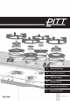
1. Overview of components.
2. Gently push the sealing ring around
the edge of the heat shield. Make sure
the ring is attached to the entire edge of
the shield. Repeat this for all the shields.
!
3. Overview of the set screws, divided
in 3 groups that will be referred to later
on.
2
3
1
3
1
2
5. Place the heat reflectors inside the
cut-outs and gently position the unit
beneath the worktop. Make sure the heat
conductor stays in position.
!
6. Make sure the flanges are concentric
inside the cut-outs. WARNING if they are
off centre they will not function properly.
9. Align the cutout in the high burner
heat shield(s) with the rib inside the
burner(s) and secure it with 3 screws.
4. Lower all the set screws until they rise
just slightly above the unit. When done
place the heat conductor on top of the
unit.
11. Gently shift the unit into a position
where all gas tab pins are in the center of
their cut-outs.
21. Check the knob(s) if they have
enough space to push and turn smoothly
in the sealing scale. If not remove the
sealing scale gently and glue it again.
10 Do not separate the protective film
from the adhesive strip for the next
steps!
12. Firmly press down the control knobs
on the gas tabs with the dots facing for-
ward. Release the knob and make sure it
springs back up to its resting position.
13. After placing the knob there should
be a small gap between the bottom
of the knob and the top of the sealing
scale.
14. Tighten the frontal set screws (group
1 as shown in step 3) by turning them
clockwise. This brings the heat conduc-
tor up to the worktop.
!
15. Stop tightening the set screws when
the bottoms of all knobs are inside their
sealing scales. The knobs must be within
5-7mm above their scales.
!
16. Tighten the rear set screws (group
2 as shown in step 3) hand tight, make
sure the heat conductor make full
contact with the worktop.
!
17. Tighten the centre set screws (group
3 as shown in step 3) hand tight, make
sure the heat conductor make full
contact with the worktop.
!
19. Make sure the heat conductor makes
full contact with the worktop and sup-
port the unit with a support beam to
lower the tension on the worktop.
18. Connect the unit to gas and electricity
and ignite the burners. If the flames
extinguish after ignition check the knob
height in step 14 again.
20. Finally remove the protective film
from the sealing scale and press the knob
and scale down as a whole to make sure
they are aligned and concentric.
1
2
3
5-7mm
!
ENEN
Important!
When the control knobs are not properly adjusted the
burners will not ignite or burn evenly.
For warranty and the proper functioning of the cooking
unit ensure the mounting is as described in this manual to
the letter.
!