c50RP/c67RP, c50RX/c67RX Quick Start Guide This guide walks you through the basic setup needed to get your new Planar displays up and running. Detailed information is contained in the Installation & Configuration Guide, which is in a CD-ROM on the back of this guide. Planar Systems, Inc. 1195 NW Compton Drive Beaverton, OR 97006-1992 Phone: +1-503-748-1100 Toll-free Phone: +1-866-475-2627 Fax: +1-503-748-5532 www.planar.
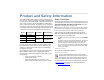
Product and Safety Information The c50RP/c67RP, c50RX/c67RX are a family of digital monitors with a 50" (c50RP or c50RX) or 67" (c67RP or c67RX) diagonal screen size. The c50RP/c67RP is an SXGA+ format, with a 1400 x 1050 resolution. The c50RX/c67RX is an XGA format, with a 1024 x 768 resolution. The displays can be configured in arrays up to two units high without additional support, and any number of units wide, which makes them ideal for many command/control room and digital signage applications.
Before you unpack your displays, you should have a detailed plan of how the displays are to be configured.
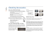
3 Checking Accessories Checking Accessories Accessories With Each Display Brackets Check for the following items included in your accessory box: The following brackets are available: • • • • • • • • This guide and the Installation & Configuration Guide CD on the back of this guide Remote control (with the batteries already installed) Power cord (for use in North America) VGA cable (15-pin cable for analog computer pictures) DVI-D cables Plastic spacers used for front access installations M8 x 8mm flat
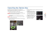
Installing the Option Key The Option key for Planar’s Big PictureTM and/or for SiFi is shipped separately and installed on site. The Option key can be installed without removing the control board. 1 Attach a ground strap to your wrist and the chassis. 2 Turn off the power on the c50R/c67R and remove the power cord. WARNING! Always turn off power and remove the power cord when adding or removing an electronic part. 3 Remove the two screws and the small plate on the bottom of the control board.
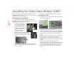
Installing the Video Input Module (VIM) The optional VIM is shipped separately and installed on site. WARNING! Always turn off power and remove the power cord when adding or removing an electronic part. the 5 Installing VIM Removing the Control Board 7 Remove the cover of the control board. It is a snug fit. Installing the VIM 1 Slide the VIM in its space and press it into its connector on the main control board. 1 Attach a ground strap to your wrist and the chassis.
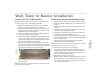
Wall, Tower or Banner Installation Installing the Second and Subsequent Rows Note: Detailed instructions for wall, tower or banner installation can be found on the Installation & Configuration Guide CD. 1 Unpack only the displays that will be in this row. (page 2) 2 Make sure all VIMs and Option keys are installed on each display. 3 Release the optical engines from their shipping position. (page 7) 4 For front access systems, put plastic spacers on the top of the units, before stacking more units.
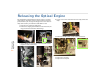
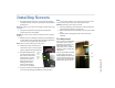
Releasing the Optical Engine The c50R/c67R is shipped with the optical engine in a lockeddown position. You must release it and put it in the operation position before you can align the image to the screen. You normally do this before you install the c50R/c67R in a wall. 4 To gain access to the area below the rear lamp, remove the lamp. 1 From the rear, remove the back panel. 2 Remove the shipping foam from the back of the unit; the large piece first and then the small wedge.
Installing Screens 1 Using two people, remove the screen from the packing case. Grab near the corners as you lift the screen from the packing case. Note: We suggest you save the screen packaging until the entire array is installed. 2 Cut open the protective envelope. Be careful not to scratch the screen or the frame. Caution: The screen is heavy, delicate and expensive. Take care when handling. 3 Remove the screen from the envelope and carefully place it aside.
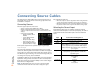
Connecting Source Cables All cabling for the c50R/c67R must be run through the rear of the display. You can run cables as the rows go up or when the installation is complete.
Each display may draw up to 2.0A at 115V or 1.0A at 230V. For countries outside of North America, it is the responsibility of the installer to provide the power supply cord certified for use in the destination country. The power switch and power receptacle are located at the left rear of the display. Connect a power cable to the power supply. The power supply is auto-ranging, so it works with any source from 100 to 240 VAC, 50 to 60 Hz.
the 11 Using Remote & Menus Using the Remote and Menus Using the Remote Control Using the Menus The remote control works much like a remote control for a TV or DVD player, but it does more. Among other things, it opens menus, changes values and moves the image. The c50R/c67R’s menus and functions are arranged in groups and can be accessed through grouped functions or by using direct access keys. The starting point for accessing menus is the MENU button on the remote.
Selecting a Source In this guide, a source is any type of picture. It might be an analog computer image, a video processor, a VCR or DVD, or it might be a DVI picture from a computer. 2 With SOURCE highlighted, press the + button to open the SOURCE submenu. Note: The SOURCE submenu displays to the right of the PICTURE Selecting the Source Automatically menu. briefly displays that it has scanned that connector and then proceeds to the next connector.
Adjusting Levels for Analog Sources Levels for 13 Adjust Analog Sources This page applies to analog RGB (computer) pictures only. The levels are best adjusted semi-automatically. For analog RGB pictures, the levels for black and white vary from one computer to another, or from one video processor to another. They even vary between video outputs from a multiple-output video card in a computer. Your pictures will not look their best on the c50R/c67R until you adjust for these differences.
Adjusting Input Levels and Position Adjusting Levels for Video Sources Video sources are adjusted best if a color bar test pattern is available from the video source: the DVD or VCR player. If not, you will have to adjust by eye and the “feel” of the picture. Note: When a video source is selected, Auto Setup Options are not available. Adjustments must be made manually. Adjusting the Picture 1 Select a video source in the PICTURE menu. 2 Press LEVEL on the remote to open INPUT LEVELS.
Color Balancing for Multiple Displays Color balancing makes the individual displays in an array show the same colors. Colors vary slightly from one display to the next, because of slight variations in the lamps and DLP engines. Color balancing can compensate for this. There are two methods to color balance a wall: • • Manual color balance Auto color balance (ACB) Manual Color Balancing 15 Color Balancing To color balance, you only have to match whites and grays.
Troubleshooting Use the following troubleshooting tables to diagnose and resolve common problems. If your screen shows black or a test pattern Do This 1 On the remote, press MONITOR. 2 On the remote, press CURTAIN once. If the message does not disappear, press CURTAIN again. Result Explanation/Further Action Possible Cause Confirm that the power cable is connected and the power switch is on. The lamps may not be lit. On the remote, press ON.
Changing a Lamp 1 Using the remote, turn off the lamp and allow the cooling fans to stop (about one minute) before proceeding. WARNING! Never remove a lamp that is still lit. Caution: In the dual-lamp system, it is possible to remove and replace the lamp that is not being used while the other lamp is on. Be careful. Use UV protective eye wear. Also, be aware that lamps are very hot and can stay hot for some time after they are turned off.
Changing an Air Filter (Rear Access) Changing an Air Filter (Front Access) The air filter is in the back of the unit below the power cord. The air filter is in the rear of the unit below the power cord. 1 Using the remote, turn off the lamp and allow the cooling fans to stop (about one minute) before proceeding. 2 Power down the unit and remove the power cord. 3 If necessary, lift up the cables so they are not in the way of the air filter. 4 Pull straight up on the air filter to remove it.
19 Conformity Declaration of Conformity Manufacturer's Name: Manufacturer's Address: declares that the products Model Numbers: conforms with the provisions of: Planar Systems, Inc.