® Owners Manual For All Electric Models READ AND SAVE THESE INSTRUCTIONS
® READ AND SAVE THESE INSTRUCTIONS FOR ELECTRIC MODELS PAC2K482S, PACHR3600, PAC2K361S, PAC2K363S, PAC2K36HPVS, PAC2K24HPVS, PAC2K16HPVS, PAC2K163SHD, PAC163SVT, PACJS1600, PACJS2400, PAC2KCYC01, PAC2KCYC01A, PACCYC02, PACCYC02A, PACCYC03, PACCYC03A PACCYC04, PACCYC04A INCLUDES EXPORT MODELS PACCYC01-22050, PACCYC01-22060, PACCYC01-22050A, PACCYC01-22060A, PACJS160022050, PACJS160022060, PACJS240022050, PACJS240022060, PAC161SVT22050, PAC161SVT22060, PACCYC02-22050, PACCYC02-22060, PACCYC02-22050A, PACCYC0
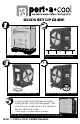
® QUICK SET UP GUIDE MODEL # ________ _______________ ________________ U.S. PAT. U.S. PAT. www.port-a-cool.com 1-800-695-2942 936-598-5651 FRAGILE! HANDLE W ITH CARE FORK MU ST BE FLA T ON FLO OR Remove box and pallette Position unit on level surface Fill sump or attach water hose Plug unit into appropriate outlet For setup, pads should appear wet before starting the fan. Check the water gauge* (see instructions for model setup in this manual) to monitor water level in tank.
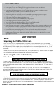
SAFE OPERATION To reduce the risk of electric shock, fire or injury: • Do not operate any unit with a damaged cord or plug. Discard unit or return to an authorized service facility for examination and/or repair. • Do not run cord under carpeting. Do not cover cord with throw rugs, runners, or similar coverings. Arrange cord away from traffic area where it will not be tripped over. • Read instructions and labels carefully.
Electrical Connection PORT-A-COOL® UNIT MUST BE IN UPRIGHT POSITION WITH COOLING PADS INSTALLED! All models utilize a single power cord and control switches. Before connecting the plug to an outlet, ensure that there is no standing water where the cord may lie or the operator is standing. The use of separate multiple outlet devices are not recommended. When making electrical connections, ensure that local and national codes are adhered to. Use only with GFCI Protected Receptacles.
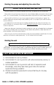
Starting the pump and adjusting the water flow CAUTION - DO NOT RUN PUMP WHEN SUMP IS DRY Once the sump tank is full, moving the pump switch to the “ON” position will turn on the pump. When initially turning on the pump, the level in the sump will drop suddenly and restart the flow of supply water. This is a normal condition, as the cooling pads require a large amount of water for proper wetting. When the PORT-A-COOL® unit is new, the new pads will require an initial ‘breaking-in’ period.
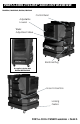
PORT-A-COOL CYCLONE® 3000 UNIT OVERVIEW PAC2KCYC01, PAC2KCYC01A, PACCYC04, PACCYC04A Control Panel Adjustable Louvers Water Adjustment Valve Electrical Plug Also applies to Cyclone 3200 PACCYC04 AND PACCYC04A Hose Connection Locking Casters PORT-A-COOL OWNER’S MANUAL • PAGE 5
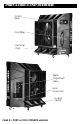
PORT-A-COOL CYCLONE® 2000 UNIT OVERVIEW PACCYC02, PACCYC02A, PACCYC03, PACCYC03A Control Panel Water Adjustment Valve Hose Connection Adjustable Louvers Locking Casters Electrical Plug Also applies to Cyclone 2200 (PACCYC03 AND PACCYC03A) Also applies to Cyclone 2200 PACCYC03 AND PACCYC03A 16” VERTICAL TANK UNIT OVERVIEW Control Panel Water Adjustment Valve Electrical Plug Cord Wrap Locking Casters This unit does NOT have a hose connection.
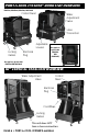
PORT-A-COOL JETSTREAM® UNIT OVERVIEW Control Panel Water Adjustment Valve Adjustable Louvers Cord Wrap Hose Connection Electrical Plug Locking Casters Control Panel Water Adjustment Valve Adjustable Louvers Cord Wrap Hose Connection Electrical Plug Locking Casters PORT-A-COOL OWNER’S MANUAL • PAGE 7
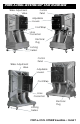
PORT-A-COOL® UNIT OVERVIEW Control Panel Cord Wrap Electrical Plug Water Adjustment Valve Hose Connection Locking Casters PAGE 8 • PORT-A-COOL OWNER’S MANUAL
PORT-A-COOL® HURRICANE UNIT OVERVIEW WATER ADJ.
HURRICANE® 3600 USER INTERFACE 1 7 2 6 3 5 4 The user interface includes touch sensitive buttons for operation of the Port-A-Cool Islander. The user interface also includes status indicator LEDs and a 7-segment LED display to show the cooling unit’s status. 1 Power The green Power LED is illuminated when the unit is plugged in. 2 Speeds The buttons control the air velocity of the unit. Beginning with “Lo”, or 50% air flow, up to “Hi” or 100% airflow and increasing in five percent increments.
MAINTENANCE & STORAGE Very little maintenance is required on the PORT-A-COOL® unit. Cleanliness is the most important part of a maintenance program. Keeping the unit clean will do more than any other single item to keep your unit in peak operating condition. The rugged, corrosion-resistant construction of the unit and industrial grade components ensure low maintenance characteristics. In excessively dusty or dirty environments, optional filters are available from your distributor or at www.port-a-coolparts.
TECHNICAL SUPPORT Technical support and service is available directly from your distributor or call PORT-A-COOL, LLC Technical Support Hot Line at 888-266-5243 for the distributor nearest you. You may also contact the Support Hot Line for consultation on troubleshooting and parts replacement. Please have serial number and model number of unit available. WARRANTY AND REPLACEMENT PARTS Port-A-Cool® Unit Limited Warranty All Port-A-Cool® units are warrantied for one full year from date of purchase.
TROUBLESHOOTING Troubleshooting The PORT-A-COOL® unit consist of three systems — the fan system, the electrical system, and the water system. It is important to determine which system of the PORT-A-COOL® unit the problem is associated with. Certain problems may be associated with more than one system. Since several things may cause a particular problem (i.e., the pump is not running), when determining which system that the problem is associated with, first define the problem.
FAN SYSTEM This section is divided into the two categories of fans used on all PORT-A-COOL® models: Direct Drive and Belt Drive. Both have some symptoms in common, and both have problems that are particular to each. BELT DRIVE MODELS PROBLEM CHECK Fan motor won’t run and Power cord, makes no sound. switches, circuit breaker, etc. SOLUTION Check switch connection Reconnect power, reset breaker. Fan motor won’t run and makes a humming sound. Blade in contact with shroud Check mounting bolts.
WATER SYSTEM The water system consists of three primary elements: 1) Water Delivery System, 2) Spray Bar Assembly; 3) Pump. Troubleshooting of this system is fairly simple. The Water Delivery System consists of two assemblies: A) The Water Inlet Assembly and B) The Plumbing Assembly. The Water Inlet Assembly is made up of three components: 1) The Bulkhead Fitting, 2) The Float Valve Connection Hose, and 3) The Float Valve.
SPRAY BAR ASSEMBLY (ALL MODELS) PROBLEM CHECK SOLUTION Too many dry streaks in the pads. Holes in spray bar blocked by foreign material. Remove and clean spray bar. Clean individual holes. Water spitting from the unit. Hose connection loose. Tighten hose. Replace hose and washer. Reseat spray bar end caps Excess water in air Pad Installation coming from the fan. Pads must be installed according to air flow direction label on the pad.
BRONZE PUMP (PAC2K36HZ or PAC2K48HZ) PROBLEM CHECK SOLUTION Pump motor will not run when switch is turned on. Power cord, switches, circuit breaker, etc. Reconnect power, reset breaker. Pump motor hums when Air Locked. switch is turned on, but does not pump water. Pump/Motor locked. Disconnect hose at base of pump, run pump to release air, then reconnect. Replace pump/motor. Pump makes loud noise while running Pump bearings. Object in impeller housing. Replace pump. Clear object.
® FREQUENTLY ASKED QUESTIONS Q. WHAT ASSEMBLY IS REQUIRED? A. None. PORT-A-COOL® units are ready to use right out of the box. Q. HOW DO I PREPARE MY PORT-A-COOL® UNIT FOR STORAGE? A. Drain the unit, dry out the pads and place the unit, preferably covered, in a dry place for the winter season. For more details, please call our Tech Support Hotline at 1-888-COOL-AID. Q. I JUST HOOKED UP MY PORT-A-COOL® UNIT FOR THE FIRST TIME AND THERE’S AN UNPLEASANT ODOR! WHAT’S WRONG? A.
FREQUENTLY ASKED QUESTIONS (continued) Q. WHAT IS THE BEST ENVIRONMENT FOR THE PORT-A-COOL® UNIT TO PRODUCE THE MOST COOL AIR? A. For optimum performance, the temperature should be 85˚ F or higher and the relative humidity should be below 75%. However, PORT-A-COOL® units will reduce the temperature in almost any environment, making it more pleasant. Q. WHAT IS THE DIFFERENCE BETWEEN EVAPORATIVE COOLING AND MISTING SYSTEMS? A.
FREQUENTLY ASKED QUESTIONS (continued) Q. WHAT IS THE AMOUNT OF MOISTURE PRODUCED BY A UNIT? A. An increase in humidity of approximately two to five percent is produced, depending on the temperature and humidity of the environment. This increase is not noticeable in a ventilated area where the air produced by the unit is exhausted. Q. HOW LONG WILL THE WATER SUPPLY LAST IN THE SUMP TANK? A.
PACCYC02A, PACCYC03, PACCYC03A ITEM# PART # DESCRIPTION ITEM# PART # DESCRIPTION 1 BLOWER-02 BLOWER HOUSING - CYCLONE2000 18 MOTOR-016-01 CYCLONE2000 - 2SPD MOTOR 2 BLOWER-WHL-2CW CYCLONE2000 BLOWER WHEEL (PART 1) 19 PAC-PLB-14 INLET HOSE ADAPTER for CYCLONE2000 3 BLOWER-WHL-3CCW CYCLONE2000 BLOWER WHEEL (PART 2) 20 PAD6019/22 KUUL PAD SET FOR CYCLONE2000 4 BONNET-06 22.
PAC2KCYC01A, PACCYC04, PACCYC04A ITEM# 1 PART # BASE-CYCLONE DESCRIPTION CADDY FRAME ITEM# 20 PART # DESCRIPTION MOTOR-MNT-BND-2 CYCLONE QUAD-MOTOR BELLY BAND 2 BLOWER-01 BLOWER HOUSING 21 PAC-PLB-14 INLET HOSE ADAPTER 3 BLOWER-WHL-01 BLOWER WHEEL 22 PAD6022.5/26 KUUL PAD SET FOR CYCLONE 4 BONNET-05 BONNET 23 PAD-SCREEN-CYL CYCLONE UNIT PAD SCREEN 5 BOX-UL-02 2 SPD UL ELECTRICAL BOX 24 POLY-FTG-06 90 DEG.
ITEM# PART # DESCRIPTION ITEM# CASTER BASE ASSEMBLY FOR JS/VT PART # DESCRIPTION 1 BASE-JS/VT 21 POWERCORD-02 10FT POWER CORD W/DOME STRAIN RELIEF 2 BLADE-ASSM-08 JS 16” BLADE 22 PAC-PLB-01 INLET HOSE ADAPTER 3 BONNET-03 SPRAY BAR BONNET FOR 16” PAC 23 PAD6024/G 16” PAC REPLACEMENT PAD (3) 4 BOX-UL-03 VAR SPD ELECTRICAL BOX 24 POLY-FTG-06 90DEG FITTING FOR SIGHT TUBE 5 CASTERS-HD-4 4” HEAVY DUTY NON-LOCKING CASTER 25 PRES-REG-01 INLET WATER REGULATOR 6 CASTERS-HD-4L 4” HEA
ITEM# PART # DESCRIPTION ITEM# PART # DESCRIPTION 1 BASE-JS-24 CASTER BASE ASSEMBLY 20 MOTOR-012-06 24” HP MOTOR 2 BLADE-ASSM-24 24” JS FAN BLADE 21 PAC-PLB-01 INLET HOSE ADAPTER 3 BONNET-02 SPRAY BAR BONNET FOR 24” PAC 22 PAD6036/G 24” REPLACEMENT PAD 4 BOX-UL-03 VAR SPD ELECTRICAL BOX 23 POLY-FTG-06 90DEG.
ITEM# PART # DESCRIPTION ITEM# PART # DESCRIPTION 1 BASE-JS/VT CASTER BASE ASSEMBLY FOR JS/VT 17 PAD6024/G 16” PAC REPLACEMENT PAD 2 BONNET-03 SPRAY BAR BONNET FOR 16” PAC 18 POLY-FTG-06 90DEG FITTING FOR SIGHT TUBE 3 BOX-UL-01 3SPD ELECTRICAL BOX 19 PUMP-0140-1 PUMP ASSEMBLY FOR 16” UNIT 4 CASTERS-HD-4 4” JS/VT HEAVY DUTY NON-LOCKING CASTER 20 PUMP-ACC-17 JS/VS PUMP BRACKET 5 CASTERS-HD-4L 4” JS/VT HEAVY DUTY LOCKING CASTER 21 S-006 12-14 BLACK TEC SCREW 5/16 -18x3/4 TRUS
ITEM# 1 PART # BONNET-03 DESCRIPTION SPRAY BAR BONNET ITEM# 15 PART # POWERCORD-01 DESCRIPTION 16’ POWER CORD W/STRAIN RELIEF 2 BOX-UL-01 3 SPD ELECTRICAL BOX 16 PRES-REG-01 WATER PRESSURE REGULATOR 3 CLAMP-01 1/2” CLAMP FOR PLASTIC TUBE 17 PUMP BRACKET PLASTIC PUMP COVER/BRACKET 4 CTRL-3SPD-02 3-SPD HARNESS W/SALZER SWITCH 18 PUMP-0150-1 PUMP 1/70HP W/NETTING 5 DRAIN-PLUG-01 DRAIN PLUG 16 PAC 19 PVC-ADP-01 3/4 X 1/2 ADAPTER 6 FAN-ASSM-15 16” VT FAN BLADE 20 S-004 1/4-20 X
ITEM # PART # DESCRIPTION ITEM # PART # DESCRIPTION 1 BASE-2K24 CADDY 20 LOCKNUT-FNG-516 5/16-18 FLANGE NYLON INSERT LOCK NUT 2 BLADE-ASSM-02 VOSTERMAN 24” FAN BLADE ASSY. (33deg.
ITEM# PART # DESCRIPTION ITEM# PART # DESCRIPTION 1 BASE-2K36 CADDY 21 MOTOR-MNT-01 MOUNT FOR 36” MOTOR 2 BEARING-FAN-01 BEARING FOR 24” & 36” PAC 22 N-516-NYLOK 5/16” NYLOCK NUT FOR CASTERS BRASS INLET FITTING 3 BELT2K-38-01 A-38 FAN BELT 23 PAC-PLB-01 4 BONNET-01 SPRAY BAR BONNET 24 PAD6048/G PAD FOR 36” PAC (5 per unit) 5 BOX-UL-02 1 SPD ELECTRICAL BOX 25 POWERCORD-01 POWER CORD ASSEMBLY 6 BRACE-36-02 BONNET BRACE 26 PRES-REG-01 WATER PRESSURE REGULATOR 7 BRACE-3
ITEM# PART # DESCRIPTION ITEM# PART # DESCRIPTION 1 BASE-2K36 CADDY 22 MOTOR-MNT-01 MOUNT FOR 36” MOTOR 2 BEARING-FAN-01 BEARING FOR 24”/36” FAN BLADE ASSEMBLY 23 N-516-NYLOK 5/16” NYLOCK NUT FOR CASTERS 3 BELT2K-38-01 A-38 FAN BELT 24 PAC-PLB-01 BRASS INLET FITTING 4 BONNET-01 SPRAY BAR BONNET 25 PAD6048/G PAD FOR 36” PAC (5 per unit) 5 BOX-UL-01 3 SPD ELECTRICAL BOX 26 POWERCORD-01 16’ ELECTRICAL CORD 6 BRACE-36-02 BONNET BRACE 27 PRES-REG-01 WATER PRESSURE REGULAT
ITEM # PART # DESCRIPTION CADDY ITEM # PART # DESCRIPTION 1 BASE-2K36 21 MOTOR-012-05 1/2 HP DIRECT DRIVE VOSTERMAN MOTOR 2 BLADE-ASSM-01 VOSTERMAN 36” FAN BLADE ASSEMBLY 22 N-516-NYLOK 5/16-18 NYLOK NUT 3 BONNET-01 SPRAY BAR BONNET FOR 36” PAC 23 PAC-PLB-01 BRASS INLET FITTING 4 BOX-UL-03 ELECTRICAL BOX 24 PAD6048/G PAD FOR 36” PAC (5 per unit) 5 BRACE-36-02 BONNET BRACE 25 POWERCORD-01 ELECTRICAL CORD FOR PAC 6 CASTERS-HD-4 HEAVY DUTYSWIVEL CASTER 26 PRES-REG-01 WATE
NEW 2012 PACHR3600 11 30 3 20 2 33 36 35 14 18 7 38 27 6 17 15 26 37 24 25 13 1 8 22 28 16 23 31 10 12 4 21 19 32 29 5 5 39 9 37 ITEM # PART # DESCRIPTION ITEM # PART # DESCRIPTION 1 BASE-SD-36 CASTER BASE ASSEMBLY 36” (HURRICANE) 21 MOTOR-034-01 36” SD 3/4HP VAR SPD MOTOR (HESSAIRE) 2 BONNET-04 SPRAY BAR BONNET FOR 48” PAC 22 PAC-PLB-01 BRASS INLET FITTING 3 BRACE-48-03 BONNET BRACE FOR 48” UNIT 23 PAD6048/G PAD FOR 36” PAC (5 per unit) 4 CASTERS-HD
ITEM# 1 PART # BASE-2K48 DESCRIPTION CADDY ITEM# 21 PART # N-516-NYLOK DESCRIPTION 5/16-18 NYLOK NUT FOR CASTERS 2 BELT2K-45-01 A-45 FAN BELT 22 PAC-PLB-01 BRASS INLET FITTING 3 BONNET-04 SPRAY BAR BONNET 23 PAC-PLB-02 BLACK PLUMBING ASSEMBLY 4 BOX-UL-02 2 SPD ELECTRICAL BOX 24 PAD6060/G PAD FOR 48” PAC (6 per unit) 5 BRACE-48-03 BRACE FOR BONNET 25 POWERCORD-01 ELECTRICAL POWER CORD 6 CASTERS-8 8” CASTERS 26 PRES-REG-01 WATER PRESSURE REGULATOR 7 CASTERS-8L 8” LOCKING
WIRING DIAGRAM for HURRICANE MODEL PORT-A-COOL OWNER’S MANUAL • PAGE 33
WIRING DIAGRAM for VARIABLE SPEED MODELS PAGE 34 • PORT-A-COOL OWNER’S MANUAL
WIRING DIAGRAM for ONE-SPEED MODELS PORT-A-COOL OWNER’S MANUAL • PAGE 35
WIRING DIAGRAM for TWO-SPEED MODELS PAGE 36 • PORT-A-COOL OWNER’S MANUAL
WIRING DIAGRAM for THREE-SPEED MODELS PORT-A-COOL OWNER’S MANUAL • PAGE 37
® Port-A-Cool® Products and Accessories and KÜÜL® Pads Cooling Media are manufactured by Port-A-Cool, LLC P.O. Box 2167 • 709 Southview Circle • Center, TX 75935 Phone 936-598-5651 • 800-695-2942 www.port-a-cool.