
Product Manual


OPERATION
To reduce the risk of injury, turn unit off and disconnect it from power source
before installing and removing accessories, before adjusting or when making repairs. An
accidental start-up can cause injury.
Do not use router bits with a diameter in excess of 2-1/8" (29mm) in this tool.
GRIPPING LOCATIONS (FIG. 3, 16, 18)
1001 BASE and 6931 PLUNGE BASE: Grip both knob handles (GG) while operating.
6911 "D" Handle Base: Grip "D" Handle (MM) and knob handle (GG) while operating.
The "D" Handle router base has two positions for the knob to accommodate right or left hand use.
INSTALLING THE BIT (1001 BASE)
Projectile hazard. Only use bits with shanks that match the installed collet.
Smaller shank bits will not be secure and could become loose during operation.
This tool is provided with two collets that accept a 1/4" (6.35 mm) or 1/2" (13 mm) shank bit.
1. To remove the motor unit from the base unit:
(a) Open the clamp (A) Fig. 1.
(b) While holding the base, turn the power unit COUNTER-CLOCKWISE until the lower pin
(B) in the motor housing is disengaged from groove in base.
(c) Lift the power unit free from the base unit.
2. Clean and insert the shank of the bit into the collet until the shank bottoms, then back it out
approximately 1/16" (1.6 mm).
3. Lay the power unit on its side on a bench with the collet pointing AWAY from you.
4. Place one wrench on the flats of the chuck with the opposite end of the wrench resting on the
bench to your left (Fig. 2).
5. Place the other wrench on the collet and tighten counter-clockwise. Tighten the collet nut
securely to prevent the bit from slipping.
6. To remove the bit, reverse the procedure.
Never tighten the collet without first installing a router bit in it. Tightening an empty
collet, even by hand, can damage the collet.
INSTALLING THE MOTOR (1001 BASE)
1. Open the clamp (A) Fig. 1 and set the power unit in the base unit.
2. Align the lower pin (B) Fig. 1 of the power unit with the groove in the base.
3. Rotate the power unit clockwise into the base until the upper guide pins are set in the groove of
the base.
4. Close the clamp.
ADJUSTING THE DEPTH OF CUT (1001 BASE)
1. Open the clamp (A) Fig. 3.
2. Hold the base (E) and turn the power unit (F) Fig. 3 counter-clockwise until the tip of the bit is
above the bottom of the base.
3. Set the tool on a flat surface.
4. Turn the power unit (F) Fig. 3 clockwise until the bit touches the work.
5. Close the clamp (A) Fig. 3.
6. Rotate the depth adjusting ring (C) Fig. 3 until the zero-line is opposite the index line (D) on the
housing.
7. Open the clamp (A) Fig. 3.
8. Tip the router so that the bit is clear of the work surface. Turn the power unit (F) Fig. 3 clockwise
until the index line (D) on the motor housing reaches the desired depth indicated on the ring.
9. Close the clamp (A) Fig. 3.
NOTE: Setting the index line to 1/4" on the ring means the cutting edge of the bit is exposed 1/4"
(6.4 mm) below the base.
ADJUSTING THE SUBBASE ALIGNMENT (ALL ROUTERS)
Applications using a template guide require the bit to be centered in the guide. This, in turn, requires
the center hole in the subbase to be in line with the collet of the motor unit. Your model has an
adjustable subbase that has been aligned at the factory. The fixed-base router comes with the
large hole.
1. Loosen the subbase mounting screws (G) Fig. 4 just enough to allow the subbase (H) to move.
2. Open the clamp (A) Fig. 4 (or screw (EE) Fig. 17) and adjust the power unit so that the collet
nut (I) Fig. 4 engages the center hole in the subbase (H). Allow the subbase to center itself on
the collet nut. Close the clamp or tighten the clamp screw firmly.
3. Tighten the subbase mounting screws (G) Fig. 4 securely.
INSTALLING THE MOTOR (6931 PLUNGE BASE)
1. Support the motor clamp (J) Fig. 5 and loosen the motor clamp screw (K) Fig. 5 approximately
1/2" (13 mm) with the hex wrench (supplied).
2. Insert the motor unit into the base with the switch positioned at the front of the left handle.
Align the four pins (O) Fig. 7 (two of which are shown) in the motor case with the slots (P) Fig.7
in the base.
3. Seat the motor in the base and tighten the motor clamp screw.
REMOVING THE MOTOR (6931 PLUNGE BASE)
1. Remove the clamp screw (K) Fig. 5, flat washer, lock washer (L), and clamp-locking nut (M)
Fig.6.
2. Insert the hex wrench (Q) Fig. 8 to contact the locking plate (N) Fig. 6. Tap lightly to release
and remove the locking plate.
3. Slide the motor out of the base.
4. Reattach the clamp screw, lock washer, flat washer, locking plate and clamp locking nut to the
base and tighten lightly.
ADJUSTING THE DEPTH OF CUT (6931 PLUNGE BASE)
1. Loosen the depth rod locking knob (R) Fig. 9, and the depth indicator knob (U), allowing the
depth rod (V) to contact one of the turret stops (S). Normally the deepest desired cut is set
with the depth rod resting on the shortest turret stop (Y) Fig. 10. The other two fixed stops (X)
Fig. 10 provide reduced cutting depths of 1/4" (6.4 mm) and 1/2" (13 mm) respectively. You
can adjust the three stops (W) Fig. 10 to any desired height. You can utilize any combination
of fixed and/or adjustable stops to achieve the desired depths required for a particular job.
Do not change the turret stop while the router is running. This will place your hands
too near the cutter head.
2. Release the plunge mechanism by pulling the locking lever (Z) Fig. 11A to the left. Lower the
plunge mechanism until the router bit touches the work surface. Release the lever and push it
to the right to lock the mechanism in this position.
3. Tighten the depth-rod locking knob.
4. Position the depth indicator (T) Fig. 9 at the "0" position and tighten the knob.
5. Loosen depth-rod locking knob (R) Fig 9. Raise the indicator until it aligns with the graduation
representing the desired depth of plunge. (The example in Fig. 9 shows setting for 1" plunge.)
6. Turn the lower travel-limiting nut (AA) Fig. 12 until it is approximately 1/4" (6.4 mm) above the
top of the the plunge housing. While holding the lower nut, turn the upper nut (BB) until it
"jams" against the lower nut (AA) Fig. 12.
Jam the travel-limiting nuts together to prevent movement (caused by vibration) which
could prevent full bit retraction.
Set the travel limiting nuts so that bit can be retracted into the base of the router, clear
of the workpiece.
DO NOT attempt to increase the plunge travel by readjusting the stop nut. Increasing
the travel beyond 2-1/2" (63.5 mm) can cause the mechanism to jam. NEVER remove the stop nut.
Motor can disengage resulting in loss of control.
ADJUSTING THE PLUNGE LOCKING LEVER (6931 PLUNGE BASE)
You can adjust the plunge-locking mechanism to reposition the lever (in the locked position), or to
compensate for wear.
1. While holding the lever in the upright position, remove the retaining screw (CC) Fig. 13.
Continue to hold the lever through the remaining steps.
2. Use an 1/8" hex wrench (not furnished) to turn the adjustment screw (DD) Fig. 14 counter-
clockwise approximately 1/2 turn.
3. Move the lever to the desired locked position and tighten the adjustment screw.
4. Remove the hex wrench and replace the retaining screw.
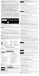
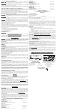
FIG. 1
FIG. 2
A
B
FIG. 11
FIG. 3
C
D
F
E
FIG. 4
H
A
I
G
FIG. 5
K
L
J
FIG. 6
M
N
FIG. 7
O
P
FIG. 8
Q
FIG. 9
R
U
T
V
S
FIG. 10
X
W
Y
Z
FIG. 11A
FIG. 12
BB
AA
FIG. 13
CC
FIG. 14
DD
FIG. 15
B
EE
A
GG
GG
FIG. 16
JJ
KK
HH
F
C
D
EE
E
FIG. 17 FIG. 18
FF
II
JJ
KK
II
GG
LL
MM
MM
GG
FF