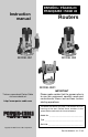
ESPAÑOL: PÁGINA 23 FRANÇAISE : PAGE 45 Instruction manual Routers MODEL 892 MODEL 891 MODEL 8931 To learn more about Porter-Cable visit our website at: http://www.porter-cable.com IMPORTANT Please make certain that the person who is to use this equipment carefully reads and understands these instructions before starting operations. The Model and Serial No. plate is located on the main housing of the tool. Record these numbers in the spaces below and retain for future reference. Model No.
TABLE OF CONTENTS IMPORTANT SAFETY INSTRUCTIONS . . . . . . . . . . . . . . . . . . . . . . . . . .2 SAFETY GUIDELINES . . . . . . . . . . . . . . . . . . . . . . . . . . . . . . . . . . . . . . . .3 GENERAL SAFETY RULES . . . . . . . . . . . . . . . . . . . . . . . . . . . . . . . . . . .4 ADDITIONAL SPECIFIC SAFETY RULES . . . . . . . . . . . . . . . . . . . . . . . .6 CARTON CONTENTS . . . . . . . . . . . . . . . . . . . . . . . . . . . . . . . . . . . . . . . .8 FUNCTIONAL DESCRIPTION . . . . . . . . .
SAFETY GUIDELINES - DEFINITIONS It is important for you to read and understand this manual. The information it contains relates to protecting YOUR SAFETY and PREVENTING PROBLEMS. The symbols below are used to help you recognize this information. indicates an imminently hazardous situation which, if not avoided, will result in death or serious injury. indicates a potentially hazardous situation which, if not avoided,could result in death or serious injury.
GENERAL SAFETY RULES Read all instructions. Failure to follow all instructions listed below may result in electric shock, fire and/or serious injury. The term "power tool" in all of the warnings listed below refers to your mains-operated (corded) power tool or battery-operated (cordless) power tool. SAVE THESE INSTRUCTIONS 1) Work area safety a) Keep work area clean and well lit. Cluttered or dark areas invite accidents.
GENERAL SAFETY RULES continued d) Remove any adjusting key or wrench before turning the power tool on. A wrench or a key left attached to a rotating part of the power tool may result in personal injury. e) Do not overreach. Keep proper footing and balance at all times. This enables better control of the power tool in unexpected situations. f) Dress properly. Do not wear loose clothing or jewelry. Keep your hair, clothing and gloves away from moving parts.
ADDITIONAL SPECIFIC SAFETY RULES 1. 2. 3. 4. 5. 6. 7. 8. 9. 10. 11. 12. 13. 14. 15. 16. 17. 18. Hold power tools by insulated gripping surfaces when performing an operation where the cutting tool may contact hidden wiring or its own cord. Contact with a "live" wire will make exposed metal parts of the tool "live" and shock the operator. Use clamps or other practical way to secure and support the workpiece to a stable platform.
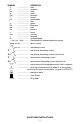
SYMBOL V ........................ A ........................ Hz ........................ W ........................ kW ........................ F ........................ µF ........................ l ........................ g ........................ kg ........................ bar ........................ Pa ........................ h ........................ min ........................ s ........................ n0 ........................ …/min or …min-1 .........
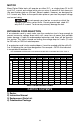
MOTOR Many Porter-Cable tools will operate on either D.C., or single phase 25 to 60 cycle A.C. current and voltage within plus or minus 5 percent of that shown on the specification plate on the tool. Several models, however, are designed for A.C. current only. Refer to the specification plate on your tool for proper voltage and current rating. Do not operate your tool on a current on which the voltage is not within correct limits. Do not operate tools rated A.C. only on D.C. current.
FUNCTIONAL DESCRIPTION FOREWORD Porter-Cable routers are designed for continuous, rugged operation to handle the most demanding production applications. ASSEMBLY NOTE: This tool is shipped completely assembled. No assembly time or tools are required. SELECTING THE BIT The 891 series of routers accommodates bits with 1/4“ and 1/2“ diameter shanks. A collet is also available that will accommodate bits with 3/8“ diameter shanks.
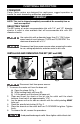
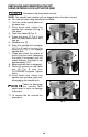
INSTALLING AND REMOVING THE BIT USING SPINDLE LOCK ACTUATOR (892) Disconnect tool from power source. NOTE: The spindle lock actuator will not engage when the tool is turned on. Turn tool off when using spindle lock actuator. 1. Turn the router upside down on its motor cap. 2. Push down and rotate the spindle lock actuator (A) Fig. 3 into place. 3. Open the clamp (B) Fig. 4. 4. Press the lever (C) Fig. 4 and push the base down as far as it can go. 5. Release lever (C). 6.
INSTALLING THE MOTOR Disconnect tool from power source. 1. 2. 3. 4. Open the clamp (A) Fig. 1 and set the power unit in the base unit. Align the rack and pin (C) Fig. 1 of the power unit with the grooves in the base, pull the lever (B) Fig. 1, and lower the motor into the base. Close the clamp (A). Reverse the procedure to remove. ADJUSTING DEPTH OF CUT Disconnect tool from power source. 1. 2. Open the clamp (A) Fig. 6.
8931 PLUNGE BASE VACUUM HOSE A standard 1" vacuum hose (A) Fig. 8A can be attached to the dust port (B) Fig. 8A to connect the tool to a vacuum cleaner or dust collection system. A B Fig. 8A INSTALLING AND REMOVING THE BIT Disconnect tool from power source. 1. 2. 3. Stand the router upside down on its motor cap (Fig. 8B). Clean and insert the shank of the bit into the collet until the shank bottoms. Then back it out approximately 1/16". Press the spindle lock button (A) Fig.
INSTALLING AND REMOVING BITS USING SPINDLE LOCK ACTUATOR WHEN ROUTER IS TABLE-MOUNTED Disconnect tool from power source. NOTE: The spindle lock actuator will not engage when the tool is turned on. Turn tool off when using spindle lock actuator. 1. 2. 3. 4. 5. 6. 7. 8. Reach under table and pull down and rotate the spindle lock actuator (E), Fig. 10 into F place. E Loosen the depth rod locking knob (A) Fig. 10 and ensure the D depth rod (B) Fig. 10 is pushed down all the way. Tighten knob.
2. 3. 4. 5. Release the plunge mechanism by pulling the locking lever (A) Fig. 14 down. Lower the plunge mechanism until the router bit touches the work surface. Release the lever and E E push it to the right to lock the mechanism in this position. Tighten the depth-rod locking knob (A) Fig. 11. C Position the depth indicator (C) Fig. 11 at the “0” position and tighten the knob (C) Fig. 11.
Adjust the plunge locking mechanism in the following manner: A B A B Fig. 15 Fig. 16 1. Hold the plunge locking lever (A) Fig. 15. 2. Insert 1/8" hex wrench (not furnished) through the center of the plungelocking bolt (B) Fig. 15 into the adjustment screw, and turn counterclockwise approximately one turn. 3. Push in on the plunge locking lever (A) Fig. 16 to expose the head of plunge-locking bolt (B) Fig. 16. 4. While holding plunge-locking lever in (A) Fig.
STARTING AND STOPPING THE MOTOR Before starting the tool, clear the work area of all foreign objects. Also keep a firm grip on the tool to resist starting torque. Two switches (A and B) Fig. 19 turn this tool “ON” and “OFF”. Additionally, the upper switch (A) will automatically turn the tool “OFF” if the tool is placed upside down on a surface. The lower switch (B) Fig. 19 is convenient for the operator to turn the tool “ON” or “OFF” with the thumb of the left hand while holding the tool (Fig. 16).
USING THE TOOL IMPORTANT: Before using the tool, consider the kind and amount of material to be removed. More than one cut may be necessary to avoid overloading the motor. Before beginning the cut on the actual workpiece, make a sample cut on a piece of scrap lumber. This will allow you to see the finished cut and to check dimensions. Always be sure the work is rigidly clamped or otherwise secured before making a cut.
INSTALLING THE OPTIONAL GRIPVAC™ (892) GripVac Parts 1. 2. 3. 4. 5. 6. 7. 8. 9. 1 Router base Dust port GripVac handle Removed handle and screw Dust deflector Sub-base with screws Hex screw (2) Shoulder washer Hex nut 10 3 4 9 8 2 5 11 7 1. Use a 5/16" hex wrench to loosen the screw in the handle (A) Fig. 25. Remove the handle from the router base. Place the handle and screw aside for use later if needed. 2. Remove the plastic plug from the dust port (2) Fig. 24. 3. Remove the screws (B) Fig.
SOFT START This router has a “Soft Start” feature designed to minimize startup reaction torque. TEMPLET GUIDES A wide variety of templet guides is available for use in pattern and templet routing operations. A typical combination bit, templet guide, and locknut are illustrated in Fig. 29. LOCKNUT ROUTER BASE TEMPLET GUIDE ROUTER BIT SUB-BASE Fig. 29 Disconnect tool from power source. To install, insert the templet guide in the center hole of the router base and secure in place with a locknut.
ROUTER PEDESTAL You can attach the inverted back half of the case to a workbench with screws through the holes (H) Fig. 30 In this configuration, storage for a wrench (A) Fig. 31, spare collet (B), and 1/4" and1/2" router bits (C) is available. You can cut out the center of the router parking pad (D) with a sharp utility knife to allow for storage of the router with a bit installed. To store the height adjustment handle, drill a 13/32" diameter hole at (E) Fig. 31.
TROUBLESHOOTING For assistance with your tool, visit our website at www.porter-cable.com for a list of service centers or call the Porter-Cable help line at 1-800-487-8665. MAINTENANCE KEEP TOOL CLEAN Periodically blow out all air passages with dry compressed air. All plastic parts should be cleaned with a soft damp cloth. NEVER use solvents to clean plastic parts. They could possibly dissolve or otherwise damage the material. Wear ANSI Z87.1 safety glasses while using compressed air.
SERVICE REPLACEMENT PARTS When servicing use only identical replacement parts. For a service parts list or to learn more about Porter-Cable visit our website at www.porter-cable.com SERVICE AND REPAIRS All quality tools will eventually require servicing, or replacement of parts due to wear from normal use. For assistance with your tool, visit our website at www.porter-cable.com for a list of service centers or call the Customer Care Department at 1-800-487-8665.
PORTER-CABLE • DELTA SERVICE CENTERS (CENTROS DE SERVICIO DE PORTER-CABLE • DELTA) (CENTRE DE SERVICE PORTER-CABLE • DELTA) Parts and Repair Service for Porter-Cable • Delta Power Tools are Available at These Locations (Obtenga Refaccion de Partes o Servicio para su Herramienta en los Siguientes Centros de Porter-Cable • Delta) (Locations où vous trouverez les pièces de rechange nécessaires ainsi qu’un service d’entretien) ARIZONA Tempe 85282 (Phoenix) 2400 West Southern Avenue Suite 105 Phone: (602) 437-12