
Instruction manual

6
energy and angle associated without activation
of the chain brake during kickback. Activated
angle represents chain stopping time relative to
activation angle of chain break and resulting
kick angle of saw . In all cases lower CKA val-
ues represent a safer operating environment
for the user.
The following guide bar and chain combina-
tions meet kickback requirements of CSA
Standards Z62.1, Z62.3, & ANSI B175.1 when
used on saws listed in this manual. Use of bar
and chain combinations other than those listed
is not recommended and may not meet the
CKA requirements per standard.
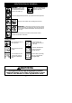
Computed kickback angle (CKA) Table
PP5020AV
BAR
P/N Length CHAIN P/N
MODEL
CKA without chain brake
20″ 17_
577179801 577180501
NOTE: To comply with Federal OSHA Reg-
ulations for Commercial Logging, a chain
brake is required and shall not be removed or
otherwise disabled.
SAFETY NOTICE: Exposure to vibrations
through prolonged use of gasoline powered
hand tools could cause blood vessel or nerve
damage in the fingers, hands, and joints of
people prone to circulation disorders or
abnormal swellings. Prolonged use in cold
weather has been linked to blood vessel
damage in otherwise healthy people. If
symptoms occur such as numbness, pain,
loss of strength, change in skin color or texture,
or loss of feeling in the fingers, hands, or joints,
discontinue the use of this tool and seek
medical attention. An anti-vibration system
does not guarantee the avoidance of these
problems. Users who operate power tools on
a continual and regular basis must monitor
closely their physical condition and the
condition of this tool.
SPECIAL NOTICE: Y our saw is equipped
with a temperature limiting muffler and spark
arresting screen which meets the require-
ments of California Codes 4442 and 4443. All
U.S. forest land and the states of California,
Idaho, Maine, Minnesota, New Jersey ,
Oregon, and Washington require by law that
many internal combustion engines to be
equipped with a spark arresting screen. If you
operate a chain saw in a state or locale where
such regulations exist, you are legally respons-
ible for maintaining the operating condition of
these parts. Failure to do so is a violation of the
law . Refer to the SERVICE section for
maintenance of the spark arresting screen.
Failure to follow all Safety Rules and
Precautions can result in serious injury. If
situations occur which are not covered in this
manual, use care and good judgement. If you
need assistance, contact your authorized
service dealer or call 1-800--554--6723.
STANDARDS: This saw is listed by Under-
writer’s Laboratories, Inc., in accordance with:
ANSI B175.1--2000 American National
Standards for Gasoline--Powered Chain
Saws -- Safety Requirements
CSA Z62.1--03 Chain Saws -- Occupational
Health and Safety
CSA Z62.3--04 Chain Saw Kickback Occu-
pational Health and Safety
ASSEMBLY
Protective gloves (not provided) should be
worn during assembly.
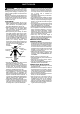
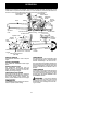
NOTE: CHAIN BR AKE MUST BE
DISENGAGED BEFORE CLUTCH
COVER CAN BE REMOVED OR RE-
INSTALLED ON THE CHAIN SAW.
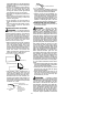
TO DISENGAGE CHAIN BRAKE,
PULL T HE FRONT HAND GUARD
BACK TOWARD THE FRON T HAN-
DLE AS FAR AS POSSIBLE (SEE
ILL U S T R ATIO N ).
Engaged
Disengaged
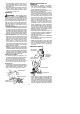
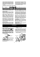
ATTACHING THE BUMPER SPIKE
(If not already attached)
The bumper spike may be used as a pivot
when making a cut.
1. Move ON/STOP switch to the STOP
position.
2. Disengage chain brake.
3. Loosen and remove the chain brake
nuts and the clutch cover from the saw.
NOTE: If clutch cover can not be easily re-
moved from the chain saw, ensure chain brake
is disengaged by pulling the front hand guard
back toward the front handle as far as possible.
4. Attach the bumper spike with the two
screws as shown.
Clutch Cover
Bar
Nuts
Bumper Spike