IMPORTANT MANUAL Do Not Throw Away OWNER'S MANUAL MODEL NUMBER: PR270 SNOW THROWER WARNING: Read the Owner's Manual and follow all Warnings and Safety Instructions. Failure to do so can result in serious injury. Always Wear Eye Protection During Operation Gasoline containing up to 10% ethanol (E10) is acceptable for use in this machine. The use of any gasoline exceeding 10% ethanol (E10) will void the product warranty. 586 61 40-27 Rev.
IMPORTANT Safe Operation Practices for Walk-Behind Snow Throwers This snow thrower is capable of amputating hands and feet and throwing objects. Failure to observe the following safety instructions could result in serious injury. WARNING: Snow throwers have exposed rotating parts, which can cause severe injury from contact, or from material thrown from the discharge chute. Keep the area of operation clear of all persons, small children and pets at all times including startup.
6. When cleaning, repairing or inspecting the snow thrower, stop the engine and make certain the collector/ impeller and all moving parts have stopped. Disconnect the spark plug wire and keep the wire away from the plug to prevent someone from accidentally starting the engine. 7. Do not run the engine indoors, except when starting the engine and for transporting the snow thrower in or out of the building. Open the outside doors; exhaust fumes are dangerous. 8.
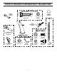
PARTS PACKED SEPARATELY IN CARTON (1) MULTIWRENCH (180684) (2) SHEAR BOLTS 1/4-20 x 1-3/4 (585511801) (2) LOCKNUTS 1/4-20 (73800400) (3) KNOB 581697501 SAFTEY IGNITION KEY (S) (443059) (2) CARRIAGE BOLTS 5/16-18 x 2 1/4” (587359001) (2) HANDLE KNOBS (189713) (1) LOCKNUT 3/8 (585691001) (1) CABLE GUIDE (581897301) 4 (1) LOCKNUT 5/16-18 (73970500) (1) CARRIAGE BOLT 5/16-18 x 5/8 (585832001) (1) LOCKNUT 1/4-20 (585691401) (1) SHOULDER BOLT 1/4-20 (585832201) (1) SPRING (184505)
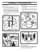
ASSEMBLY / PRE-OPERATION Read these instructions and this manual in its entirety before you attempt to assemble or operate your new snow thrower. Reading the entire manual will familiarize you with the unit, which will assist you in assembly, operation and maintenance of the product. Your new snow thrower has been assembled at the factory with the exception of those parts left unassembled for shipping purposes. All parts such as nuts, washers, bolts, etc.
ASSEMBLY / PRE-OPERATION INSTALL DISCHARGE CHUTE / CHUTE ROTATOR HEAD (See Fig. 4 and 5) NOTE: The multi-wrench provided in your parts bag may be used to install the chute rotator head. 1. Place discharge chute assembly on top of chute base with discharge opening toward front of snow thrower. 2. Position chute rotator head over chute bracket. If necessary, rotate chute assembly to align square and pin on underside of chute rotator head with holes in chute bracket. 3.
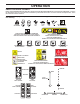
OPERATION KNOW YOUR SNOW THROWER READ THIS OWNER'S MANUAL AND ALL SAFETY RULES BEFORE OPERATING YOUR SNOW THROWER. Compare the illustrations with your snow thrower to familiarize yourself with the location of various controls and adjustments. Save this manual for future reference. These symbols may appear on your snow thrower or in literature supplied with the product. Learn and understand their meaning.
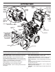
OPERATION MUFFLER AUGER CONTROL LEVER POWER CORD PLUG GASOLINE FILLER CAP DISCHARGE CHUTE CONTROL LEVER ELECTRIC START BUTTON CHOKE CONTROL ON / OFF SWITCH DRIVE SPEED CONTROL LEVER DEFLECTOR REMOTE CONTROL LEVER TRACTION DRIVE CONTROL LEVER PRIMER SAFETY IGNITION KEY FUEL SHUT-OFF VALVE RECOIL STARTER HANDLE CHUTE DEFLECTOR CLEAN-OUT TOOL DISCHARGE CHUTE HANDLE KNOB NOTE: ITEMS ABOVE ARE SHOWN IN THEIR TYPICAL LOCATION ON THE ENGINE. ACTUAL LOCATION MAY VARY WITH THE ENGINE ON YOUR UNIT.
OPERATION TO CONTROL SNOW DISCHARGE (See Fig. 11) The operation of any snow thrower can result in foreign objects thrown into the eyes, which can result in severe eye damage. Always wear safety glasses or eye shields while operating your snow thrower or performing any adjustments or repairs. We recommend standard safety glasses or a wide vision safety mask worn over spectacles.
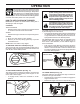
OPERATION USING THE CLEAN-OUT TOOL (See Fig. 13) In certain snow conditions, the discharge chute may become clogged with ice and snow. Use the clean-out tool to dislodge this blockage. TO MOVE FORWARD AND BACKWARD (See Fig. 14) SELF-PROPELLING, forward and reverse movement of the snow thrower, is controlled by the traction drive control lever located on the left side handle. • Squeeze traction drive control lever to handle to engage the drive system.
OPERATION BEFORE STARTING THE ENGINE TO ADJUST SKID PLATES (See Fig. 15) NOTE: The wrench provided in your parts bag may be used to adjust the skid plates. Skid plates are located on each side of the auger housing and adjust the clearance between the scraper bar and the ground surface. Adjust skid plates evenly to proper height for current surface conditions.
OPERATION TO START ENGINE • Ensure fuel shut-off valve is in the “OPEN” position. Your snow thrower engine is equipped with both a 120 Volt A.C. electric starter and a recoil starter. The electric starter is equipped with a three-wire power cord and plug and is designed to operate on 120 Volt A.C. household current. • Ensure your house is a 120 Volt A.C. three-wire grounded system. If you are uncertain, consult a licensed electrician. 5. Pull recoil starter handle quickly.
MAINTENANCE LUBRICATION CHART GENERAL RECOMMENDATIONS ➀ ➁ ➂ The warranty on this snow thrower does not cover items that have been subjected to operator abuse or negligence. To receive full value from the warranty, operator must maintain snow thrower as instructed in this manual. Some adjustments will need to be made periodically to properly maintain your snow thrower. All adjustments in the Service and Adjustments section of this manual should be checked at least once each season.
MAINTENANCE Check the crankcase oil level before starting the engine and after each five (5) hours of continuous use. Tighten oil fill cap / dipstick securely each time you check the oil level. TO CHANGE ENGINE OIL Determine temperature range anticipated before next oil change. All oil must meet API service classification SG–SL. • Be sure snow thrower is on level surface. • Oil will drain more freely when warm. • Catch oil in a suitable container.
SERVICE AND ADJUSTMENTS To replace the shear bolts: 1. Disengage all controls and move throttle control to STOP position. Wait for all moving parts to stop. 2. Remove safety ignition key and disconnect spark plug wire from spark plug. Place wire where it cannot come in contact with spark plug. 3. Align holes in impeller hub with holes in impeller shaft and install two (2) new 2" shear bolts. Install 1/4-20 locknuts and tighten securely.
SERVICE AND ADJUSTMENTS TO REPLACE BELTS AUGER BELT REPLACEMENT (See Fig. 20) TO REMOVE AUGER BELT 1. Remove upper 5/16” bolts and lower 1/4” bolts from both sides of the frame assembly. Do not discard bolts. 2. Loosen but DO NOT REMOVE lower 5/16” bolts on both sides of the frame assembly. 3. Remove the auger belt from the engine pulley. 4. Tip the back section down. The front section will tip forward at the same time, as the bottom bolt acts as a hinge between the front and back sections.
SERVICE AND ADJUSTMENTS AFTER REPLACING BELT(S) 1. INSTALL BELT COVER and two (2) screws. Tighten securely. 2. INSTALL DISCHARGE CHUTE – See “INSTALL DISCHARGE CHUTE / CHUTE Rotator HEAD” in the Assembly section of this manual. TO REMOVE WHEELS (See Fig. 22) • Remove the wheel pin and retainer pin and remove wheel from axle. NOTE: To seal punctures or prevent flat tires due to slow leaks, tire sealant may be purchased from your local parts dealer. Tire sealant also prevents tire dry rot and corrosion.
SERVICE AND ADJUSTMENTS TO ADJUST SPEED SELECT AND DRIVE ENGAGEMENT CABLE TENSION (See Fig. 23) After many hours of use, if first gear seems to slip or seems too slow, adjustments may need to be made to the Speed Select and Drive Engagement cable tensions to shorten their lengths. To adjust the Speed Select cable: 1. Adjust cable tension by loosening the jam nut next to the turn buckle. 2. Grasp the short section and hold while turning the long section to lengthen the adjuster. 3.
STORAGE Immediately prepare your snow thrower for storage at the end of the season or if the unit will not be used for 30 days or more. • Empty the fuel tank by starting the engine and letting it run until the fuel lines and carburetor are empty. • Never use engine or carburetor cleaner products in the fuel tank or permanent damage may occur. • Use fresh fuel next season. NOTE: Fuel stabilizer is an acceptable alternative in minimizing the formation of fuel gum deposits during storage.
TROUBLESHOOTING See appropriate section in manual unless directed to an authorized service center/department. PROBLEM Does not start CAUSE 1. Fuel shut-off valve (if so equipped) in OFF position. 2. Safety ignition key is not inserted. 3. Out of fuel. 4. Throttle in STOP position (or ON/OFF switch is OFF). 5. Choke in OFF position. 6. Primer not depressed. 7. Engine is flooded. 8. Spark plug wire is disconnected. 9. Bad spark plug. 10. Stale fuel. 11. Water in fuel. CORRECTION 1.
REPAIR PARTS SNOW THROWER - MODEL PR270 (96192006801) AUGER HOUSING / IMPELLER ASSEMBLY 1 3 5X 2 KEY NO. 1 2 3 PART NO. 581 63 74-02 532 41 53-71 872 27 05-05 4 532 15 53-77 DESCRIPTION AUGER HOUSING SCRAPER BAR CARRIAGE BOLT 5/16-18 X .625 GR5 NUT 5/16-18 KEY NO. 1 2 PART NO. 532 42 11-06 532 42 11-07 DESCRIPTION AUGER 27 LH AUGER 27 RH 4 5X 05.09.011-C 2 1 05.09.006-C NOTE: All component dimensions given in U.S. inches. 1 inch = 25.4 mm IMPORTANT: Use only Original Equipment Manufacturer (O.
REPAIR PARTS SNOW THROWER - MODEL PR270 (96192006801) AUGER HOUSING / IMPELLER ASSEMBLY 15 14 14 10 8 8 13 6 16 14 3 4 11 9 14 13 5 12 9 13 1 2 7 7 7 6 05.09.009-F NOTE: All component dimensions given in U.S. inches. 1 inch = 25.4 mm IMPORTANT: Use only Original Equipment Manufacturer (O.E.M.) replacement parts. Failure to do so could be hazardous, damage your snow thrower and void your warranty.
REPAIR PARTS SNOW THROWER - MODEL PR270 (96192006801) AUGER HOUSING / IMPELLER ASSEMBLY KEY NO. 1 2 3 4 5 6 7 8 9 10 11 12 13 14 15 16 PART NO.
REPAIR PARTS SNOW THROWER - MODEL PR270 (96192006801) AUGER HOUSING / IMPELLER ASSEMBLY 1 KEY NO. 1 2 3 PART NO. 532 19 21-99 532 40 54-00 532 19 41-89 KEY NO. 1 2 3 PART NO. 532 42 04-78 532 41 19-39 584 29 94-01 KEY NO. PART NO. 1 2 3 532 18 40-93 532 18 40-94 585 69 17-01 4 585 69 13-01 DESCRIPTION TOOL CLEANOUT CLIP CLEANOUT TOOL SCREW HEX WASHER 13-16 X 5/8 2 05.09.039-A 3 1 1 2 2 3 3 3 3 05.09.007-A 2 1 4 DESCRIPTION AUGER BEARING BEARING PLUG SCREW HI-LO WASHD 5/16-14 X 1.
REPAIR PARTS SNOW THROWER - MODEL PR270 (96192006801) CONTROL PANEL / DISCHARGE CHUTE 4 1 4 9 2 8 6 8 7 5 6 3 5 05.08.002-D KEY NO. 1 2 3 4 5 6 7 8 9 PART NO. 581 12 83-01 587 42 87-01 587 34 38-01 581 72 61-01 532 19 79-91 532 42 81-24 581 32 94-01 532 42 33-03 585 80 83-01 DESCRIPTION CABLE CONTROL DRIVE CABLE CONTROL AUGER CABLE CONTROL SPEED BOLT SHOULDER 1/4 CLIP CABLE FASTENER PUSH .250 PIN CLEVIS 5/16 HAIRPIN PIN CLEVIS 1/4 NOTE: All component dimensions given in U.S. inches. 1 inch = 25.
REPAIR PARTS SNOW THROWER - MODEL PR270 (96192006801) CONTROL PANEL / DISCHARGE CHUTE 5 5 1 5 7 2 4 3 4 05.08.003-D KEY NO. 1 2 3 4 5 6 7 PART NO. 581 68 03-01 581 32 94-01 877 10 08-12 532 42 33-03 584 65 22-01 586 68 21-01 587 13 08-01 4 6 DESCRIPTION CABLE ROTATOR ASM PIN CLEVIS 5/16 X 7/8 PIN CLEVIS 1/4 X 3/4 HAIRPIN SOFT ZINC CLIP CONDUIT DOUBLE WASHER PIN CLEVIS 5/16 X 1 NOTE: All component dimensions given in U.S. inches. 1 inch = 25.
REPAIR PARTS SNOW THROWER - MODEL PR270 (96192006801) CONTROL PANEL / DISCHARGE CHUTE 3 3 2 2 1 4 5 KEY NO. PART NO. DESCRIPTION 1 2 3 4 5 580 66 47-01 532 43 17-62 812 00 00-14 581 15 12-01 532 19 79-91 CABLE INTERLOCK PIN GROOVED E-RING SPRING RETURN CLIP CABLE BLACK 05.08.001-B NOTE: All component dimensions given in U.S. inches. 1 inch = 25.4 mm IMPORTANT: Use only Original Equipment Manufacturer (O.E.M.) replacement parts.
REPAIR PARTS SNOW THROWER - MODEL PR270 (96192006801) CONTROL PANEL / DISCHARGE CHUTE 1 2 KEY NO. PART NO. 1 581 13 12-01 2 817 06 04-10 3 581 32 95-01 KEY NO. PART NO. 1 581 12 81-04 2 3 532 19 41-89 581 92 87-01 3 2 DESCRIPTION CONSOLE BASE MULTI CONTROL SCREW TA SEMI GIMLE 1/4-20 X .62 SCREW HEX WASHER 13-16 X 1.50 05.07.003-A 3 2 3 2 DESCRIPTION CONSOLE COVER PPRO NO LIGHT SCREW HI-LO 13-16 X 5/8 CLIP PANEL 1 05.07.007-A NOTE: All component dimensions given in U.S. inches.
REPAIR PARTS SNOW THROWER - MODEL PR270 (96192006801) CONTROL PANEL / DISCHARGE CHUTE 4 5 1 5 1 3 4 2 3 KEY NO. 1 2 3 4 5 PART NO. 587 46 30-01 581 20 81-01 585 69 07-01 532 43 17-62 812 00 00-14 KEY NO. 1 2 3 4 5 6 7 PART NO. 581 12 39-02 581 24 16-02 581 32 97-01 581 32 96-01 586 66 89-01 584 46 84-02 587 03 13-01 DESCRIPTION LEVER CONTROL DSST LEVER PIVOT CONTROL ASM SCREW HEX HD 10-24 X 1.50 PIN GROOVED E-RING 2 05.08.
REPAIR PARTS SNOW THROWER - MODEL PR270 (96192006801) CONTROL PANEL / DISCHARGE CHUTE 8 10 10 9 7 *11 *13 *12 2 3 7 4 4 *15 1 *14 KEY NO. PART NO.
REPAIR PARTS HANDLES SNOW THROWER - MODEL PR270 (96192006801) 1 2 KEY NO. 1 2 3 PART NO. 581 12 36-04 532 18 97-13 587 35 90-01 KEY NO. 1 2 PART NO. 581 12 35-04 817 00 06-12 3 581 62 20-02 4 817 00 05-10 DESCRIPTION UPPER HANDLE HANDLE KNOB STD BLACK BOLT 5/16-18 X 1.75 CONCAVE HEAD 3 2 05.06.001-E 1 3 2 4 2 DESCRIPTION LOWER TUBE SCREW HEX WASH HD 3/8-16 X .75 CHUTE ROTATOR SUPPORT ASM BOLT HEX 5/16-18 4 05.05.001-D NOTE: All component dimensions given in U.S. inches. 1 inch = 25.
REPAIR PARTS DRIVE SNOW THROWER - MODEL PR270 (96192006801) 2 6 11 10 9 7 6 8 12 13 5 14 3 15 4 1 19 2 16 12 13 18 20 13 17 05.02.001-C NOTE: All component dimensions given in U.S. inches. 1 inch = 25.4 mm IMPORTANT: Use only Original Equipment Manufacturer (O.E.M.) replacement parts. Failure to do so could be hazardous, damage your snow thrower and void your warranty.
REPAIR PARTS DRIVE SNOW THROWER - MODEL PR270 (96192006801) KEY NO. PART NO. DESCRIPTION 1 2 3 4 5 6 7 8 9 10 11 12 13 14 15 16 17 18 19 20 585 69 1501 580 75 6201 532 17 5344 872 11 0506 581 09 0901 581 09 1002 812 00 0022 581 12 1901 580 75 6101 581 09 1101 532 75 1153 812 00 0007 581 73 2701 581 31 5301 581 45 4203 581 32 8401 581 12 3001 581 44 6903 532 19 3885 521 99 1101 NUT HEX FLANGE LK 5/16-18 BEARING 9/16 I.D. 1622-2RSNR TRUNNION BEARING ASM BOLT CARRIAGE 5/16-18 X .
REPAIR PARTS DRIVE SNOW THROWER - MODEL PR270 (96192006801) 6 2 1 8 7 5 6 3 4 3 1 2 3 5 05.03.001-A KEY NO. PART NO. DESCRIPTION 1 2 3 4 5 6 7 8 532 44 49-49 581 12 23-01 812 00 00-53 581 12 22-02 532 17 12-71 532 12 47-88 532 18 92-82 581 12 20-01 WASHER 1.00 HEX BUSHING 1 SHAFT RETAINER RING GEAR 80T DRIVEN RIVET RD HD DRILLED 1/4 DIA RETAINER SPRING SQUARE KEY 1/4 X .875 AXLE SHAFT NOTE: All component dimensions given in U.S. inches. 1 inch = 25.
REPAIR PARTS SNOW THROWER - MODEL PR270 (96192006801) CHASSIS / ENGINE / PULLEYS 5 5 5 5 3 6 4 6 5 8 5 7 7 1 8 7 7 5 7 7 5 05.01.001-C 2 2 2 2 KEY NO. -- PART NO. 580 42 60-05 1 2 580 83 94-03 532 15 04-06 3 4 5 580 83 95-03 581 12 24-02 817 06 04-10 6 7 585 20 60-01 532 42 88-67 8 585 21 75-01 KEY NO. PART NO. DESCRIPTION 1 583 94 05-02 SMALL MOUNTING PLATE DESCRIPTION COMPLETE LCT ENGINE PW2HK18650178E FRAME ENGINE BOLT 3/8-16 X 1.
REPAIR PARTS SNOW THROWER - MODEL PR270 (96192006801) CHASSIS / ENGINE / PULLEYS 2 3 2 1 KEY NO. 1 2 PART NO. 587 10 54-01 585 69 11-01 3 4 532 14 50-06 532 42 30-62 DESCRIPTION BELT COVER BLACK BOLT HEX WSH THDRL 1/4-20 X 1 CABLE GUIDE PALNUT 1/4 IN 4 4 05.04.002-B NOTE: All component dimensions given in U.S. inches. 1 inch = 25.4 mm IMPORTANT: Use only Original Equipment Manufacturer (O.E.M.) replacement parts. Failure to do so could be hazardous, damage your snow thrower and void your warranty.
REPAIR PARTS SNOW THROWER - MODEL PR270 (96192006801) CHASSIS / ENGINE / PULLEYS 1 2 2 3 3 4 5 4 11 6 7 12 20 9 10 13 6 7 8 10 15 14 6 19 16 18 17 05.04.001-G KEY NO. 1 2 3 4 PART NO. 581 62 37-02 819 11 12-16 810 04 05-00 874 61 05-12 5 6 7 581 33 82-03 873 80 05-00 532 05 92-89 8 9 581 14 14-01 580 75 30-01 10 874 76 05-28 DESCRIPTION BELT KEEPER BRACKET WASHER 11/32 X 3/4 X 16 GA LOCKWASHER 5/16 SPLIT HVY CAPSCREW HEXHD 5/16-24 X .
REPAIR PARTS WHEELS SNOW THROWER - MODEL PR270 (96192006801) 2 1 KEY NO. PART NO. DESCRIPTION 1 2 580 62 77-03 580 62 76-03 WHEEL 13X4 NPS RH 1.00 K478 WHEEL 13X4 NPS LH 1.00 K478 05.15.001-A NOTE: All component dimensions given in U.S. inches. 1 inch = 25.4 mm IMPORTANT: Use only Original Equipment Manufacturer (O.E.M.) replacement parts. Failure to do so could be hazardous, damage your snow thrower and void your warranty.
REPAIR PARTS BAG OF PARTS SNOW THROWER - MODEL PR270 (96192006801) 12 8 9 10 6 7 3 4 1 2 5 11 13 05.18.004-E 1 KEY NO. PART NO. 1 2 3 4 5 6 7 8 9 10 11 12 13 -- 585 51 18-01 873 80 04-00 532 42 91-12 585 83 22-01 585 69 14-01 585 69 10-01 587 35 90-01 532 19 19-38 585 83 20-01 873 97 05-00 532 18 45-05 581 69 75-01 581 89 73-01 580 94 77-05 -- 587 42 10-04 KEY NO. 1 PART NO. 532 44 30-59 DESCRIPTION BOLT 1/4- 20 X 1.
REPAIR PARTS DECALS SNOW THROWER - MODEL PR270 (96192006801) 1 4 KEY NO. PART NO. DESCRIPTION 1 2 3 4 532 18 40-45 532 19 96-82 532 19 96-83 532 18 40-28 DECAL AUGER DECAL CHUTE DECAL AUGER SAFETY DECAL BELT GUIDE 3 2 05.16.001-A NOTE: All component dimensions given in U.S. inches. 1 inch = 25.4 mm IMPORTANT: Use only Original Equipment Manufacturer (O.E.M.) replacement parts. Failure to do so could be hazardous, damage your snow thrower and void your warranty.
REPAIR PARTS DECALS 1 SNOW THROWER - MODEL PR270 (96192006801) 4 6 1 6 3 KEY PART NO. NO. DESCRIPTION 1 3 4 6 ---- DECAL, DANGER DECAL, DANGER, DEFLECTOR DECAL, DANGER DECAL, BE H GUARD OWNER’S MANUAL, ENGLISH OWNER’S MANUAL, FRENCH OWNER’S MANUAL, SPANISH 532 19 96-83 532 19 96-82 532 18 40-45 532 18 40-28 586 61 40-27 586 61 40-31 586 61 40-46 NOTE: All component dimensions given in U.S. inches. 1 inch = 25.4 mm IMPORTANT: Use only Original Equipment Manufacturer (O.E.M.) replacement parts.
REPAIR PARTS SNOW THROWER - MODEL PR270 (96192006801) COMPLETE ENGINE-580426005 KEY PART NO. NO. 1 2 3 4 5 6 7 8 9 DESCRIPTION 532 42 05-78 CYLINDER HEAD ASSEMBLY 208CC (INCL. GASKET) 532 42 05-79 PUSH ROD & PLATE KIT (208CC) (INCL. VALVE COVER GSKT) 532 42 05-80 VALVE COVER (208CC) (INCL.
REPAIR PARTS SNOW THROWER - MODEL PR270 (96192006801) COMPLETE ENGINE-580426005 KEY PART NO. NO.
LIMITED WARRANTY The Manufacturer warrants to the original consumer purchaser that this product as manufactured is free from defects in materials and workmanship. For a period of two (2) years from date of purchase by the original consumer purchaser, we will repair or replace, at our option, without charge for parts or labor incurred in replacing parts, any part which we find to be defective due to materials or workmanship. This Warranty is subject to the following limitations and exclusions. 1.