IMPORTANT MANUAL Do Not Throw Away OWNER'S MANUAL MODEL NUMBER: P624ES SNOW THROWER WARNING: Read the Owner's Manual and follow all Warnings and Safety Instructions. Failure to do so can result in serious injury. Always Wear Eye Protection During Operation Gasoline containing up to 10% ethanol (E10) is acceptable for use in this machine. The use of any gasoline exceeding 10% ethanol (E10) will void the product warranty.
IMPORTANT Safe Operation Practices for Walk-Behind Snow Throwers This snow thrower is capable of amputating hands and feet and throwing objects. Failure to observe the following safety instructions could result in serious injury. WARNING: Snow throwers have exposed rotating parts, which can cause severe injury from contact, or from material thrown from the discharge chute. Keep the area of operation clear of all persons, small children and pets at all times including startup.
6. When cleaning, repairing or inspecting the snow thrower, stop the engine and make certain the collector/impeller and all moving parts have stopped. Disconnect the spark plug wire and keep the wire away from the plug to prevent someone from accidentally starting the engine. 7. Do not run the engine indoors, except when starting the engine and for transporting the snow thrower in or out of the building. Open the outside doors; exhaust fumes are dangerous. 8.
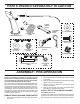
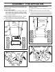
PARTS PACKED SEPARATELY IN CARTON (1) AUGER CONTROL ROD (1) MULTIWRENCH (180684) (1) DISCHARGE CHUTE (3) RETAINER SPRINGS (169675) (1) POWER CORD (198563) (2) FLAT WASHERS ROTATOR HEAD MOUNTING (2) CARRIAGE BOLTS 3/8-16 x 2.25 (1) WASHER 3/8 (19131316) (1) LOCKNUT 3/8 (73800600) SAFTEY IGNITION KEY(S) (443059) (2) HANDLE KNOBS EXTRA SHEAR BOLTS AND NUTS (2) SHEAR BOLTS 1/4-20 x 1-3/4 (192090) (2) LOCKNUTS 1/4-20 (73800400) ASSEMBLY / PRE-OPERATION 2.
ASSEMBLY / PRE-OPERATION NOTE: The multi-wrench may be used for assembly of the chute rotator head to snow thrower and making adjustments to the skid plates. INSTALL TRACTION DRIVE CONTROL ROD (See Figs. 3 and 4) The traction drive control rod is installed on the snow thrower. 1. Remove plastic tie securing rod to lower handle. 2. With top end of rod positioned under left side of control panel, push rod down and insert top end of rod into hole in drive control bracket. Secure with retainer spring.
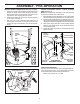
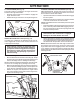
ASSEMBLY / PRE-OPERATION INSTALL DISCHARGE CHUTE / CHUTE ROTATER HEAD (See Fig. 7) NOTE: The multi-wrench provided in your parts bag may be used to install the chute rotater head. 1. Place discharge chute assembly on top of chute base with discharge opening toward front of snow thrower. 2. Position chute rotater head over chute bracket. If necessary, rotate chute assembly to align square and pin on underside of chute rotater head with holes in chute bracket. 3.
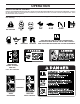
OPERATION KNOW YOUR SNOW THROWER READ THIS OWNER'S MANUAL AND ALL SAFETY RULES BEFORE OPERATING YOUR SNOW THROWER. Compare the illustrations with your snow thrower to familiarize yourself with the location of various controls and adjustments. Save this manual for future reference. These symbols may appear on your snow thrower or in literature supplied with the product. Learn and understand their meaning.
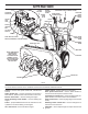
OPERATION MUFFLER ELECTRIC START BUTTON GASOLINE FILLER CAP AUGER CONTROL LEVER POWER CORD PLUG CHOKE CONTROL DISCHARGE CHUTE CONTROL LEVER DRIVE SPEED CONTROL LEVER TRACTION DRIVE CONTROL LEVER CHUTE DEFLECTOR SAFETY IGNITION KEY ON / OFF SWITCH DISCHARGE CHUTE PRIMER CHUTE DEFLECTOR KNOB FUEL SHUT-OFF VALVE RECOIL (AUXILIARY) STARTER HANDLE HANDLE KNOB CLEAN-OUT TOOL MUFFLER NOTE: ITEMS ABOVE ARE SHOWN IN THEIR TYPICAL LOCATION ON THE ENGINE.
OPERATION The operation of any snow thrower can result in foreign objects thrown into the eyes, which can result in severe eye damage. Always wear safety glasses or eye shields while operating your snow thrower or performing any adjustments or repairs. We recommend standard safety glasses or a wide vision safety mask worn over spectacles. TO CONTROL SNOW DISCHARGE (See Figs.
OPERATION TO THROW SNOW (See Fig. 13) The auger rotation is controlled by the auger control lever located on the right side handle. • Squeeze auger control lever to handle to engage the auger and throw snow. • Release the auger control lever to stop throwing snow. TO MOVE FORWARD AND BACKWARD (See Fig. 15) SELF-PROPELLING, forward and reverse movement of the snow thrower, is controlled by the traction drive control lever located on the left side handle.
OPERATION ADD GASOLINE (See Fig. 17) • Fill fuel tank to bottom of tank filler neck. Do not overfill. Use fresh, clean, regular unleaded gasoline with a minimum of 87 octane. Do not mix oil with gasoline. Purchase fuel in quantities that can be used within 30 days to assure fuel freshness. TO ADJUST SKID PLATES (See Fig. 16) NOTE: The wrench provided in your parts bag may be used to adjust the skid plates.
OPERATION 5. Pull recoil starter handle quickly. Do not allow starter rope to snap back. 6. When the engine starts, release the recoil starter handle and slowly move the choke control to the “OFF” position. Allow the engine to warm up for a few minutes. Engine will not develop full power until it has reached normal operating temperature. WARM START - RECOIL STARTER Follow the steps above, keeping the choke in the “OFF” position. DO NOT push the primer.
MAINTENANCE GENERAL RECOMMENDATIONS LUBRICATION CHART The warranty on this snow thrower does not cover items that have been subjected to operator abuse or negligence. To receive full value from the warranty, operator must maintain snow thrower as instructed in this manual. Some adjustments will need to be made periodically to properly maintain your snow thrower. At least once a season, check to see if you should make any of the adjustments described in the Service and Adjustments section of this manual.
MAINTENANCE BELTS Check belts for deterioration and wear after every 50 hours of operation and replace if necessary. The belts are not adjustable. Replace belts if they begin to slip from wear. (See “TO REMOVE BELT COVER” in the Service and Adjustments section of this manual). The belts on your snow thrower are of special construction and should be replaced by original equipment manufacturer (OEM) belts available from your nearest dealer.
SERVICE AND ADJUSTMENTS 3. Make sure the augers and all moving parts have completely stopped. To replace the capscrew/shear bolts: 1. Disengage all controls and move throttle control to STOP position. Wait for all moving parts to stop. 2. Remove safety ignition key and disconnect spark plug wire from spark plug. Place wire where it cannot come in contact with spark plug. 3. Align holes in impeller hub with holes in impeller shaft and install two (2) new 1/4-20 x 1-5/8" capscrew/shear bolts.
SERVICE AND ADJUSTMENTS TO REPLACE BELTS (See Fig. 20) The auger and traction drive belts are not adjustable. If the belts are damaged or begin to slip from wear, they should be replaced. It is recommended that the belt(s) be replaced by a service center/department. NOTE: It is recommended that both the auger and traction drive belt be replaced at the same time.
SERVICE AND ADJUSTMENTS TO REMOVE WHEELS (See Fig. 21) • Remove the wheel pin and retainer pin and remove wheel from axle. IMPORTANT: When installing wheel, be sure to use the inner most hole in axle and the wheel hub hole. To disengage drive system from the wheels (for pushing or transporting the snow thrower) remove wheel pin and retainer pin from wheel hub and insert wheel pin and retainer into the outer hole in axle only.
STORAGE Immediately prepare your snow thrower for storage at the end of the season or if the unit will not be used for 30 days or more. • Empty the fuel tank by starting the engine and letting it run until the fuel lines and carburetor are empty. • Never use engine or carburetor cleaner products in the fuel tank or permanent damage may occur. • Use fresh fuel next season. NOTE: Fuel stabilizer is an acceptable alternative in minimizing the formation of fuel gum deposits during storage.
TROUBLESHOOTING See appropriate section in manual unless directed to an authorized service center/department. PROBLEM Does not start CAUSE 1. Fuel shut-off valve (if so equipped) in OFF position. 2. Safety ignition key is not inserted. 3. Out of fuel. 4. Throttle in STOP position (or ON/OFF switch is OFF). 5. Choke in OFF position. 6. Primer not depressed. 7. Engine is flooded. 8. Spark plug wire is disconnected. 9. Bad spark plug. 10. Stale fuel. 11. Water in fuel. CORRECTION 1.
REPAIR PARTS SNOW THROWER - - MODEL NUMBER P624ES (96198004300) AUGER HOUSING / IMPELLER ASSEMBLY 5 11 11 6 7 15 14 4 16 11 12 13 11 3 8 12 17 10 1 37 9 2 9 33 37 32 34 31 9 30 31 26 29 36 27 28 23 22 21 20 25 35 22 23 24 21 18 2 (EXPLODED) 19 01.07.026-E NOTE: All component dimensions given in U.S. inches. 1 inch = 25.4 mm IMPORTANT: Use only Original Equipment Manufacturer (O.E.M.) replacement parts.
REPAIR PARTS SNOW THROWER - - MODEL NUMBER P624ES (96198004300) AUGER HOUSING / IMPELLER ASSEMBLY KEY NO. 1 2 3 4 5 6 7 8 9 10 11 12 13 14 15 16 17 18 19 20 21 22 23 24 25 26 27 28 29 30 31 32 33 34 35 36 37 PART NO.
REPAIR PARTS SNOW THROWER - - MODEL NUMBER P624ES (96198004300) AUGER HOUSING / IMPELLER ASSEMBLY 1 KEY NO. PART NO. DESCRIPTION 1 2 3 4 532 41 52-95 532 40 78-25 872 27 05-05 532 15 53-77 AUGER HOUSING SCRAPPER BAR CARRIAGE BOLT 5/16−18 X .625 NUT 5/16−18 KEY NO. PART NO. DESCRIPTION 1 2 532 42 10-72 532 42 10-73 AUGER ASSEMBLY LH 24 AUGER ASSEMBLY RH 24 3 (5x) 4 (5x) 2 01.07.001-A 2 1 01.07.017-A NOTE: All component dimensions given in U.S. inches. 1 inch = 25.
REPAIR PARTS SNOW THROWER - - MODEL NUMBER P624ES (96198004300) AUGER HOUSING / IMPELLER ASSEMBLY 2 3 1 1 2 KEY NO. PART NO. DESCRIPTION 1 2 3 532 42 04-78 532 41 19-39 532 17 95-82 AUGER BEARING BEARING PLUG SCREW 5/16−18 X 1.00 3 01.07.024-B 2 1 3 3 1 2 01.11.003-B KEY NO. PART NO. 1 2 532 43 59-51 532 42 65-89 3 872 11 05-10 DESCRIPTION PLATE SKID PLASTIC HDPE NUT 5/16-18 LARGE HEX FLANGE BLK CARRIAGE BOLT 5/16-18 X 1.25 NOTE: All component dimensions given in U.S. inches.
REPAIR PARTS SNOW THROWER - - MODEL NUMBER P624ES (96198004300) CONTROL PANEL / CHUTE 11 10 2 5 8 3 6 6 11 4 11 9 7 1 6 01.09.005-E KEY NO. 1 2 3 4 5 6 7 8 9 10 11 12 13 12 13 PART NO. 532 43 63-25 532 18 45-11 532 42 03-25 532 18 41-14 532 44 50-19 532 12 84-15 532 18 56-00 872 27 05-05 532 19 17-30 532 15 54-15 532 17 92-46 532 43 03-24 532 42 17-28 DESCRIPTION CHUTE WELDMENT DEFLECTOR WELDMENT DEFLECTOR SEAL STRAP KNOB BLACK POP RIVET SHOULDER BOLT 1/4−20 X .704 CARRIAGE BOLT 5/16−18 X .
REPAIR PARTS SNOW THROWER - - MODEL NUMBER P624ES (96198004300) CONTROL PANEL / CHUTE 2 2 1 *3 *7 *6 *4 KEY NO. 1 2 *3 *4 *5 *6 *7 PART NO. 532 42 82-72 817 50 10-10 532 42 06-78 532 40 59-32 532 42 06-75 532 42 82-73 532 42 83-10 01.09.010-B DESCRIPTION LEVER/CABLE ROTATOR ASSEMBLY SCREW 10-24 X .625 ROTATOR HEAD ROTATOR PIVOT BRACKET PULLEY PIVOT CABLE ASSEMBLY ADJUSTABLE CABLE ASSEMBLY HEAT SHIELD NOTES: 1. ITEMS INDICATED WITH AN * ARE LISTED AS REFERENCE FOR SERVICE PARTS ONLY.
REPAIR PARTS SNOW THROWER - - MODEL NUMBER P624ES (96198004300) HANDLES 5 1 6 8 7 2 5 9 3 8 6 7 8 4 9 KEY NO. 1 2 3 4 5 6 7 8 9 PART NO. 532 42 10-69 532 42 10-70 532 42 91-48 532 42 91-49 532 19 95-13 874 78 05-12 874 78 05-24 532 75 11-53 532 15 54-15 DESCRIPTION PLOW HANDLE LH PLOW HANDLE RH PANEL BRACKET LH PANEL BRACKET RH HANDLE GRIP SCREW 5/16−18 X .750 SCREW 5/16−18 X 1.50 NUT 5/16−18 WASHER KEY NO. 1 2 3 4 PART NO.
REPAIR PARTS SNOW THROWER - - MODEL NUMBER P624ES (96198004300) HANDLES 10 2 11 8 6 7 5 4 7 9 9 1 3 13 8 12 13 14 14 12 KEY NO. 1 2 3 4 5 6 7 8 9 10 11 12 13 14 PART NO. 532 41 55-39 532 42 88-59 532 42 88-60 532 41 55-46 532 42 90-98 532 41 26-77 532 42 16-13 532 16 96-75 817 06 04-10 532 41 42-80 532 41 42-81 532 17 88-99 819 13 13-16 872 12 06-18 01.08.
REPAIR PARTS SNOW THROWER - - MODEL NUMBER P624ES (96198004300) HANDLES 2 10 10 3 1 8 9 KEY NO. PART NO. DESCRIPTION 1 2 3 4 5 6 7 8 9 10 532 18 04-80 532 40 57-40 532 18 04-45 532 18 77-16 532 18 04-47 532 17 86-69 532 18 09-26 872 27 05-05 532 15 53-77 532 16 96-75 IMPELLER ROD TRACTION ROD SHIFTER ROD TOP SHIFTER ROD BOTTOM SPRING SLEEVE IMPELLER SPRING TRACTION SPRING CARRIAGE BOLT 5/16-18 X .625 NUT 5/16-18 RETAINER 4 5 7 10 5 6 01.12.001-E NOTE: All component dimensions given in U.S.
REPAIR PARTS SNOW THROWER - - MODEL NUMBER P624ES (96198004300) HANDLES 3 1 2 KEY NO. PART NO. DESCRIPTION 1 2 3 532 18 33-52 532 18 44-71 532 17 52-62 CONSOLE PANEL SCREW 10−24 X .625 SCREW 10−24 X 1.25 KEY NO. 1 2 3 4 5 6 PART NO. 532 41 62-88 532 41 45-72 532 17 88-31 532 16 96-75 817 06 04-10 532 42 18-14 DESCRIPTION INTERLOCK SPRING INTERLOCK CAM TORSION SPRING RETAINER SCREW 1/4−20 X .625 INTERLOCK STOP 3 2 01.10.001-B 4 3 2 5 1 6 01.08.
REPAIR PARTS SNOW THROWER - - MODEL NUMBER P624ES (96198004300) DRIVE 42 EXPLODED 46 2 45 48 16 17 1 18 15 11 9 9 10 8 7 12 9 11 53 13 14 47 15 49 20 22 19 53 11 4 34 23 52 53 21 6 24 5 33 23 53 3 29 30 31 35 27 24 33 32 28 26 26 38 53 36 37 4 23 50 24 24 25 54 42 43 39 44 41 40 39 01.02.013-B NOTE: All component dimensions given in U.S. inches. 1 inch = 25.4 mm IMPORTANT: Use only Original Equipment Manufacturer (O.E.M.) replacement parts.
REPAIR PARTS SNOW THROWER - - MODEL NUMBER P624ES (96198004300) DRIVE KEY NO. PART NO.
REPAIR PARTS SNOW THROWER - - MODEL NUMBER P624ES (96198004300) DRIVE 5 8 6 7 1b 4 3 8 1b 1a 6 2 3 5 4 01.03.005-C KEY NO. 1 PART NO. 532 18 82-26 1a 1b 2 3 4 5 6 7 8 532 17 93-52 532 18 42-06 532 40 26-91 532 17 46-97 532 17 98-30 817 49 05-08 532 17 12-71 532 18 92-82 532 12 47-88 DESCRIPTION AXLE ASSEMBLY (assy of 1a,1b) AXLE SHAFT ROLL PIN 3/16 SPROCKET THRUST WASHER BEARING BOLT 5/16−18 X .500 PIN SQUARE KEY RETAINER PIN NOTE: All component dimensions given in U.S. inches. 1 inch = 25.
REPAIR PARTS SNOW THROWER - - MODEL NUMBER P624ES (96198004300) CHASSIS / ENGINE / PULLEYS 2 3 2 3 1 01.00.034-A KEY NO. PART NO. -- 532 43 60-67 1 2 3 532 42 92-75 532 15 04-06 532 42 88-67 COMPLETE LCT ENGINE PW2HK18650178E FRAME BOLT 3/8-16 SCREW 5/16-18 X .750 KEY NO. 1 PART NO. 532 43 07-64 DESCRIPTION ENGINE MOUNTING PLATE KEY NO. 1 PART NO. 532 44 30-30 DESCRIPTION COVER ASSEMBLY DESCRIPTION 1 01.01.004-A 1 01.21.013-C NOTE: All component dimensions given in U.S. inches.
REPAIR PARTS SNOW THROWER - - MODEL NUMBER P624ES (96198004300) CHASSIS / ENGINE / PULLEYS 23 22 24 14 21 20 11 19 14 21 20 13 18 17 12 14 15 16 6 7 10 8 4 3 5 9 1 2 01.21.003-C KEY NO. PART NO. DESCRIPTION KEY NO. PART NO.
REPAIR PARTS SNOW THROWER - - MODEL NUMBER P624ES (96198004300) WHEELS 1 KEY NO. 1 2 PART NO. 532 44 50-27 532 44 50-28 DESCRIPTION WHEEL ASSEMBLY LH WHEEL ASSEMBLY RH 2 01.06.018-A NOTE: All component dimensions given in U.S. inches. 1 inch = 25.4 mm IMPORTANT: Use only Original Equipment Manufacturer (O.E.M.) replacement parts. Failure to do so could be hazardous, damage your snow thrower and void your warranty.
REPAIR PARTS SNOW THROWER - - MODEL NUMBER P624ES (96198004300) BAG OF PARTS 3 4 2 5 7 1 KEY NO. 1 2 3 4 5 6 7 PART NO. 532 19 85-63 532 16 96-75 532 42 91-12 873 80 06-00 819 13 13-16 532 19 20-90 873 80 04-00 DESCRIPTION POWER CORD RETAINER PIN WRENCH LOCKNUT 3/8−16 WASHER 3/8 SHEAR BOLT 1/4−20 X 1−3/4 LOCKNUT 1/4−20 KEY NO. 1 PART NO. 532 44 30-59 DESCRIPTION SAFETY IGNITION KEY KIT 6 01.14.004-B 1 01.14.009-B 1 3 2 4 1 4 2 01.14.012-A KEY NO. 1 2 3 4 PART NO.
REPAIR PARTS SNOW THROWER - - MODEL NUMBER P624ES (96198004300) DECALS 1 4 9 6 11 1 3 KEY NO. PART NO. DESCRIPTION 1 3 4 6 9 11 --- 532 18 10-37 532 18 10-35 532 18 10-42 532 18 10-33 532 42 95-91 532 42 87-16 532 44 34-79 532 44 35-32 DECAL, DANGER DECAL, DANGER, DEFLECTOR DECAL, DANGER DECAL, INSTRUCTION DECAL, CON RT SPD/LEV/PWST DECAL, CON LT WD/DEF OWNER’S MANUAL, ENGLISH OWNER’S MANUAL, FRENCH NOTE: All component dimensions given in U.S. inches. 1 inch = 25.
SERVICE NOTES 38
SERVICE NOTES 39
LIMITED WARRANTY The Manufacturer warrants to the original consumer purchaser that this product as manufactured is free from defects in materials and workmanship. For a period of two (2) years from date of purchase by the original consumer purchaser, we will repair or replace, at our option, without charge for parts or labor incurred in replacing parts, any part which we find to be defective due to materials or workmanship. This Warranty is subject to the following limitations and exclusions. 1.