CORE 50 Sweeper Scrubber Owner’s Manual PowerBoss, Inc. A Member Of The Hako Group techsupport@powerboss.com Technical Service 800-982-7141 PB # 4100004 / Rev.
PowerBoss Owner’s Manual ® The Power of Clean The Model and Serial Numbers of your machine are shown on the nameplate mounted on the machine. This information is needed when contacting Technical Support or ordering parts. For your convenience, use the space below to record the Model and Serial Numbers of your machine and the date it was placed into service.
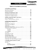
PowerBoss ® The Power of Clean CORE 50 Sweeper Scrubber OWNER’S MANUAL TABLE OF CONTENTS Warranty ................................................................... 6 S AFETY Safety Symbols ........................................................... 7 Safety Decals ............................................................. 8 Basic PowerBoss® Safety ............................................ 10 B ASIC OPER ATION CONTROL Ignition Switch ..........................................................
PowerBoss Owner’s Manual ® The Power of Clean TABLE OF CONTENTS (Continued) SCRUBBING CONTROLS Filling The Solution Tank ............................................ 15 Main Scrub Brushes ................................................... 16 Double Scrubbing ...................................................... 17 Draining The Recovery Tank........................................ 18 Cleaning The Recovery Tank ....................................... 18 Cleaning The Solution Filter .....................
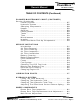
Owner’s Manual PowerBoss ® The Power of Clean TABLE OF CONTENTS (Continued) PL ANNED M AINTEN ANCE CH ART (CONTINUED) Service (Continued) Coolant System ................................................. Hydraulic System ............................................... Sweeping Components ........................................ Hopper ............................................................. Steering ........................................................... Parking Brake ...........................
PowerBoss Owner’s Manual ® The Power of Clean TABLE OF CONTENTS (Continued) SWEEP COMPONENTS (CONTINUED) Main Broom Height Adjustment ............................. 42 Main Broom Taper Adjustment .............................. 43 Main Broom Replacement..................................... 44 Side Broom Height (W ear) Adjustment ................... 4 5 Side Broom Angle Adjustment............................... 45 Side Broom Replacement .....................................
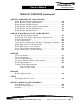
Owner’s Manual PowerBoss ® The Power of Clean TABLE OF CONTENTS (Continued) TROUBLESHOOTING Engine W ill Not Start Or Runs Roughly After Start 56 Engine Overheats ............................................. 57 Machine Moves Slowly Or Does Not Move ............ 57 Machine Creeps In Neutral ................................ 58 Brushes Do Not Turn Or Turns Very Slowly .......... 58 Little Or No Vacuum In Brush Compartment.......... 58 Loss Of Dust Control ........................................
PowerBoss Owner’s Manual ® The Power of Clean CORE 50 Sweeper Scrubber (LIMITED) PRODUCT WARRANTY PowerBoss, Inc. (hereafter known as PowerBoss) warrants that these PowerBoss machines will be free from defects in material and workmanship for a period of 24 months or 2,000 operating hours from date of installation, whichever comes first.
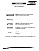
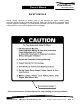
PowerBoss Owner’s Manual ® The Power of Clean SAFETY SYMBOLS Five symbols are used throughout this manual to emphasize various levels of safety information. These symbols and the meaning of each are listed below. DANGER DANGER: To warn of immediate hazards which will result in severe personal injury or death WARNING WARNING: To warn of hazards or unsafe practices which could result in severe personal injury or death.
PowerBoss Owner’s Manual ® The Power of Clean SAFETY DECALS Decals directly attached to various parts of the sweeper are highly visible safety reminders which should be read and observed. Make sure the decals are replaced if they become illegible or damaged. The decal below is located in the drive compartment. Other safety decals on you machine appear on the next page. Part Number 301854 Follow manufacturers recommendations for safe handling of cleaning materials. PowerBoss, Inc.
PowerBoss Owner’s Manual ® The Power of Clean SAFETY DECALS (Continued) Shroud of Radiator Impeller Part Number 301729 Part Number 301733 Impeller Part Number 301730 High Dump & Low Dump Hopper Part Number 301731 High Dump Hopper Part Number 301732 Shroud of Radiator Part Number 301728 PowerBoss, Inc.
PowerBoss Owner’s Manual ® The Power of Clean BASIC PowerBoss® SAFETY PowerBoss® sweepers should never be operated unless: 1. The operator is trained and authorized to operate the equipment and, 2. The equipment is free of malfuntions. Malfunctioning equipment should be removed from service. DANGER WARNING Keep cigarettes, matches and all other flame sources away from the sweeper. Gasoline, LP gas and diesel fuel are highly flammable.
Owner’s Manual PowerBoss ® The Power of Clean BASIC PowerBoss® SAFETY (Continued) 4. During cleaning and maintenance: ٭Always stop the engine and set the parking ٭ ٭ ٭ ٭ brake before servicing. Never use detergents or cleansers that are flammable or combustible. Never inflate a pneumatic tire without using a safety cage. Do not attempt any impeller adjustment unless you have shut off the engine. Never place your hands near the intake hoses or inlet when the engine is running.
PowerBoss Owner’s Manual ® The Power of Clean BASIC PowerBoss® SAFETY (Continued) 2. Travel slowly on grades. 3. Place a block or chock behind the wheels when parking on inclines. 4. Use special care when traveling on wet surfaces. 5. Observe all proper procedures for operation and maintenance of the sweeper, as outlined in this manual. 6. Remain alert at all times to people and equipment in and around your area of operation. ATTENTION! Turn the tow valve before pushing or towing.
Owner’s Manual PowerBoss ® R The Power of Clean BASIC OPERATION CONTROLS IGNITION SWITCH NOTE The ignition switch turns electrical power on for the machine. in addition, the switch cranks the engine. To start the engine, turn the key all the way clockwise to engage the starter motor. After the engine starts, release the key. The engine swing frame must be completely closed and latched to start the engine. To stop the engine turn the key all the way counterclockwise to the “OFF” position.
PowerBoss Owner’s Manual ® The Power of Clean BASIC OPERATING CONTROLS (Continued) DIRECTIONAL CONTROL PEDAL The directional control pedal controls the speed and direction of the machine. It is also used for slowing the machine or stopping. ٭To propel the machine forward, apply pressure to the front of the pedal, increasing pressure to increase speed. ٭To propel the machine backward, apply pressure to the rear of the pedal. ٭To slow or stop the machine, move the foot pedal into neutral.
PowerBoss Owner’s Manual ® R The Power of Clean SWEEPING CONTROLS SIDE BROOM SWITCH When activated the switch lowers the side broom to the floor and turns the broom on. This function only works when the main broom is also activated. MAIN BROOM SWITCH When activated this switch: ٭Opens the hopper dump door ٭Lowers the main broom to the floor. ٭Activates the broom motor. ٭Activates the impeller motor. The main broom function can be used alone or with the side broom function.
Owner’s Manual PowerBoss ® The Power of Clean SCRUBBING CONTROLS (Continued) Never use detergents or cleaners that are flammable or CAUTION combustible. Always wear safety glasses when using chemicals of any kind. NOTE MAIN SCRUB BRUSHES This machine is designed so that the scrub brushes will not turn and solution will not be delivered to the brushes while the machine is not moving. To operate the scrub brushes, follow these steps: 1. Lower the scrubheads to the floor with the scrubhead switch.
PowerBoss Owner’s Manual ® The Power of Clean SCRUBBING CONTROLS MAIN SCRUB BRUSHES (Continued) NOTE 5. Lower the squeegee with the squeegee switch. The squeegee can also be raised with the same switch. Lowering the squeegee activates the scrubbing impeller automatically. When the squeegee is raised, the impeller will continue to run for ten (10) seconds before shutting off. When machine travel stops, the scrub brushes stop rotating and solution flow is interrupted until travel resumes.
PowerBoss Owner’s Manual ® The Power of Clean SCRUBBING CONTROLS (Continued) DRAINING THE RECOVERY TANK Follow these steps to drain the recovery tank: 1. Park the machine on a level surface at an approved drainage site with the left rear of the machine beside the drain access. 2. Engage the parking brake. 3. Turn the machine OFF. 4. Locate the drain hose on the left side of the machine beneath the engine access side door. 5. Remove the flexible drain hose from its storage tray.
Owner’s Manual PowerBoss ® The Power of Clean SCRUBBING CONTROLS (Continued) CLEANING THE SOLUTION FILTER The Cleaning solution passes through a filter canister on its way to the scrub brushes. This filter can be inspected and cleaned even if the solution tank is full. This filter is located on the right side of the machine beneath the foot pedal just inside of the frame rail. 1. Locate the valve on the forward side of the filter canister (the valve closest to the broom chamber).
Owner’s Manual PowerBoss ® The Power of Clean DEBRIS HOPPER DUMP CONTROLS HIGH DUMP MODELS NOTE The lever on the front control panel is used to raise the hopper to a height up to 60” (1.52 m) and dump it. The lever is spring loaded to a center OFF position. To raise the hopper, pull back the lever to the RAISE position and hold until the hopper raises to the proper height for the dumpster or container.
Owner’s Manual PowerBoss ® The Power of Clean OPERATING PROCEDURES PRE-OPERATION CHECKS Prior to starting the engine, check the following: 1. 2. 3. 4. 5. 6. Engine oil level Engine coolant level Fuel level Hydraulic fluid level Brakes, steering and directional controls The floor beneath the machine for signs of fluid leaks Fluid levels should be correct. Brakes, steering and directional controls should be functioning properly. Hoses, lines and tanks should be free of damage and leaks.
Owner’s Manual OPERATING ON GRADES PowerBoss The Power of Clean 1. Always travel slowly. 2. Exercise extreme caution when traveling across or turning on grades 3. Use the brake pedal only for slowing the machine on grades. SWEEPING 1. Lower the Brooms ٭Lower the side broom by pressing the right side of the side broom switch. ٭Lower the main broom by pressing the right side of the main broom switch. * When sweeping extremely uneven floors, position the FLOAT lever in the lowered position. 2.
PowerBoss Owner’s Manual USING THE ROTARY TRASH RELOCATOR (RTR™) NOTE ® The Power of Clean During sweeping, if the need arises, the RTR functions can be accomplished as described below. 1. Use the directional control pedal to stop the machine on a level surface. 2. Turn the main broom OFF by placing the switch in the center “OFF” position. This rotates the dump door, causing debris to move from the rear entrance to the front wall of the hopper. TRANSPORTING THE MACHINE Loading ATTENTION! Towing 1.
Owner’s Manual PowerBoss ® The Power of Clean JACK POINTS WARNING Use jack stands to hold the machine. Do not rely on the jack alone. To jack the machine, place the jack under the front edge of the wheel well on the frame. To jack the rear of the machine, place the jack under the main frame beneath the tail lights. TIE DOWN Each of the front walls of the wheel wells have an opening for securing the machine in the front.
Owner’s Manual PowerBoss The Power of Clean CHECK ENGINE LIGHT If the yellow “Check Engine Light” illuminates, this indicates that the engine has experienced a fault. Contact your service provider and advise them of the indicator light. HYDRAULIC MANIFOLDS Most hydraulic functions are controlled by three hydraulic manifold blocks containing electronically controlled valves. These manifold blocks are located behind the hopper and can be accessed by raising the hopper and engaging the safety arm.
PowerBoss Owner’s Manual ® The Power of Clean PLANNED MAINTENANCE CHART INTRODUCTION Regular maintenance on your sweeper results in better cleaning, faster cleaning and a prolonged service life for the equipment and components.
PowerBoss Owner’s Manual ® The Power of Clean PLANNED MAINTENANCE CHART SERVICE FREQUENCY (IN HOURS) DAILY 50 100 200 (BY MAINTENANCE AREA) 500 ENGINE X Pressure wash engine For additional maintenance requirements, refer to the engine manual furnished with this manual. AIR INTAKE SYSTEM X Empty rubber dust cup of air filter element. X Clean air filter. NOTE: Clean more often in dusty conditions. X Replace air filter.
PowerBoss Owner’s Manual ® The Power of Clean PLANNED MAINTENANCE CHART (Continued) SERVICE FREQUENCY (IN HOURS) DAILY 50 100 200 500 (BY MAINTENANCE AREA) HYDRAULIC SYSTEM X Check hydraulic reservoir dipstick and fill as needed. X Replace breather cap filter element. X Replace hydraulic fluid and filter X Check functioning of directional control pedal and adjust as needed. X X Clean hydraulic fluid strainer in reservoir.
PowerBoss Owner’s Manual ® The Power of Clean PLANNED MAINTENANCE CHART (Continued) SERVICE FREQUENCY (IN HOURS) DAILY 50 100 200 (BY MAINTENANCE AREA) 500 HOPPER X Check hopper filters and clean or replace as needed. X Inspect the hopper flaps for wear or damage and replace as needed. X Inspect hopper side and frame seals for wear or damage. Adjust or replace as needed. STEERING X Check for leaks. PARKING BRAKE X Check for proper functioning and adjust as needed.
PowerBoss Owner’s Manual ® The Power of Clean PLANNED MAINTENANCE CHART (Continued) SERVICE FREQUENCY (IN HOURS) DAILY 50 100 200 500 (BY MAINTENANCE AREA) MISCELLANEOUS X Inspect latches and hinges. Tighten and lubricate as needed. X Check anti-static drag chain on rear wall of broom chamber for damage or excessive wear. Replace as needed. X Check side broom lift cable and brake cable for wear. IMPELLER X Check for hydraulic fluid leaks.
PowerBoss Owner’s Manual ® The Power of Clean SERVICE INSTRUCTIONS INTRODUCTION Maintenance requirements and service instructions for your sweeper engine are outlined in the following parts of this Maintenance Section: ٭ Air Intake System ٭ Electrical System ٭ Fuel System ٭ Coolant System ٭ Lubrication System All basic maintenance tasks are listed with their recommended frequencies on the Planned Maintenance Chart in this manual.
PowerBoss Owner’s Manual ® The Power of Clean SERVICE INSTRUCTIONS (CONTINUED) AIR INTAKE SYSTEM AIR FILTER REMOVAL 1. Turn off the engine and set the parking brake. WARNING 2. 3. 4. 5. 6. NOTE Do NOT swing the engine frame open while the engine is running. Open the engine access doors and lid. Unlatch the engine and swing open the engine frame. Locate the air filter and unclamp the dust cup retaining clamps. Remove the dust cup. Pull the air filter out of its housing.
PowerBoss Owner’s Manual ® The Power of Clean SERVICE INSTRUCTIONS (CONTINUED) ELECTRICAL SYSTEM BATTERY CLEANING 1. 2. 3. 4. Combine baking soda and water in a strong solution. Brush the solution over the battery top, including terminals and cable clamps. Make sure the solution does not enter the battery. Using a wire brush, clean the terminal posts and cable clamps. Apply a thin coating of petroleum jelly to the terminals and cable clamps. BATTERY REPLACEMENT CAUTION 1. 2. 3. 4.
Owner’s Manual PowerBoss ® The Power of Clean SERVICE INSTRUCTIONS (CONTINUED) FUEL SYSTEM WARNING 1. Never attempt to perform any service on the equipment or components until the engine is OFF, the parking brake is LOCKED, and the wheels are CHOCKED. 2. Never operate an LPG powered sweeper when any component in the fuel system is malfunctioning or leaking. 3. Never bypass safety components. 4. Replace any defective safety components before operating the sweeper. 5.
PowerBoss Owner’s Manual ® The Power of Clean SERVICE INSTRUCTIONS (CONTINUED) COOLANT SYSTEM BLOWING OUT RADIATOR FINS NOTE Make sure radiator is cool before blowing out the radiator fins with compressed air. Be careful that the radiator fins are not bent by the compressed air. Any fins that are bent should be straightened. REVERSE FLOW FLUSHING 1. At the engine, disconnect the hoses. 2. Make sure the radiator cap is on tight. 3. Using a hose clamp, clamp a flushing gun onto the lower hose. 4.
Owner’s Manual PowerBoss ® The Power of Clean SERVICE INSTRUCTIONS (CONTINUED) LUBRICATION Gasoline and LPG Engines: Use any SF or SG rated oil meeting API specifications and suited to seasonal temperatures. Refer to the Engine Manufacturer’s Operator Manual for these specifications. CHANGING ENGINE OIL 1. Stop the engine and lock the parking brake. 2. Unlatch and swing the engine frame open and secure with the locking pin. 3. Place a drain pan under the engine drain hose located on the engine pan. 4.
PowerBoss Owner’s Manual ® The Power of Clean LUBRICATION POINTS Lubrication Dump Arm Mounts Type of Lubrication Grease PowerBoss, Inc.
PowerBoss Owner’s Manual ® The Power of Clean SERVICE INSTRUCTIONS (CONTINUED) HYDRAULICS SYSTEM FILLING THE FLUID RESERVOIR NOTE 1. The reservoir is located inside the machine and is accessible through the top side door. When the machine is cool and the hopper is in the lowered position, remove the fill cap located in the top of the fluid reservoir. Fluid level should be to the grove on the dipstick attached to the fill cap. CAUTION 2.
PowerBoss Owner’s Manual ® R The Power of Clean SERVICE INSTRUCTIONS (CONTINUED) HYDRAULICS SYSTEM (CONTINUED) CHANGING THE HYDRAULIC FLUID FILTER 1. 2. 3. 4. 5. 6. Raise the hopper and engage the safety arm. Turn off the engine and engage the parking brake. Unscrew the oil filter cartridge from the mount and discard in an approved manner. The filter is located on the firewall behind the hopper. Apply a thin coating of fluid to the seal of a new filter element. Thread onto the mount and hand tighten.
PowerBoss Owner’s Manual ® The Power of Clean SERVICE INSTRUCTIONS (CONTINUED) HYDRAULICS SYSTEM (CONTINUED) ADJUSTING THE DIRECTIONAL CONTROL RETURN SPRING (CONTINUED) CAUTION 8. 9. Slide the bracket while watching the rear wheel. Continue to adjust until the rear wheel does not turn in either direction. Fine tuning may be done by loosening the locking nuts on this bracket where the cable attaches. Adjust the cable anchoring to lengthen/ shorten the cable. WARNING 9. 10. 11. 12.
PowerBoss Owner’s Manual ® The Power of Clean SERVICE INSTRUCTIONS (CONTINUED) SWEEP COMPONENTS BROOM DOOR FLAP INSPECTION NOTE 1. 2. 3. Perform this inspection when the machine is parked on a level surface. Turn the machine off and lock the parking brake. Inspect broom door flaps for wear and damage. Flap clearance should be ⅛” (3.18 mm) above the floor. Worn and damaged flaps should be replaced immediately to maintain proper dust control.
PowerBoss Owner’s Manual ® The Power of Clean SERVICE INSTRUCTIONS (CONTINUED) SWEEP COMPONENTS (CONTINUED) NOTE A rectangular shape the length of the main broom, 2” (5.08 cm) wide, indicates the main broom is properly adjusted. A pattern smaller then 2” (5.08 cm) indicates need for lower adjustment. A pattern wider than 2” (5.08 cm) indicates a need for higher adjustment. If pattern is tapered from end to end instead of rectangular, see Taper Adjustment on the next page.
PowerBoss Owner’s Manual ® The Power of Clean SERVICE INSTRUCTIONS (CONTINUED) SWEEP COMPONENTS (CONTINUED) MAIN BROOM TAPER ADJUSTMENT NOTE It is not usually necessary to perform this adjustment. However, if the main broom adjustment test shows a pattern that is tapered in length (one end is wider than the other), perform the procedures which follow. Correct Taper Pattern Incorrect Taper Pattern Main Broom Taper Patterns 1. 2. 3. 4. 5.
PowerBoss Owner’s Manual ® The Power of Clean SERVICE INSTRUCTIONS (CONTINUED) SWEEP COMPONENTS (CONTINUED) MAIN BROOM REPLACEMENT (Bristles worn to a length of 1 inch; 2.54 cm or less) 1. Turn the engine off and lock the parking brake. 2. Push the main broom float lever to the FLOAT (DOWN) position 3. Open the left broom chamber door (the door opposite the driver’s seat). 4. Remove the knob on the main broom idler mount. 5. Pull the main broom idler mount straight out to remove. 6.
Owner’s Manual PowerBoss ® The Power of Clean SERVICE INSTRUCTIONS (CONTINUED) SWEEP COMPONENTS (CONTINUED) SIDE BROOM HEIGHT (WEAR) ADJUSTMENT The side broom wear adjustment is controlled in ½” steps. These steps are accomplished using the two pins in the side broom adjusting block. 1. 2. 3. 4. Lift the hopper cover to the open position. Set the parking brake. Start the engine and lift the hopper. Stop the engine and engage the hopper safety arm. CAUTION 5. 6. 7. 8.
PowerBoss Owner’s Manual ® The Power of Clean SERVICE INSTRUCTIONS (CONTINUED) SWEEP COMPONENTS (CONTINUED) SIDE BROOM REPLACEMENT (Bristles worn to a length of 3 inches; 7.62 cm or less) NOTE 1. 2. 3. 4. 5. 6. The side broom features a quick release mechanism which enables the operator to remove the brush in seconds. Stop the machine and set the parking brake. Turn the side broom by hand until the brush retainer bar is accessible.
Owner’s Manual PowerBoss ® R The Power of Clean SERVICE INSTRUCTIONS (CONTINUED) SCRUB & WATER PICK-UP COMPONENTS WARNING Never attempt to perform any service on the equipment or components until the machine is OFF, the parking brake is LOCKED and the wheels are CHOCKED. SCRUB BRUSH REPLACEMENT The scrub brush features a quick release mechanism which enables the operator to remove the brush in seconds. NOTE 1. 2. 3. 4. 5. 6. Brushes should be replaced when the bristles are less than ½” (12.
PowerBoss Owner’s Manual ® The Power of Clean SERVICE INSTRUCTIONS (CONTINUED) SCRUB & WATER PICK-UP COMPONENTS CASTER ADJUSTMENT 1. 2. 3. 4. If only caster adjustment is required, stop the engine and set the parking brake. Loosen the wing nuts on top of the caster stems. Turn the caster stems to raise or lower the casters. If too much flare was experienced, lower the caster. If too little flare was observed, raise the casters. Adjust the casters so that both are equal in adjustment.
PowerBoss Owner’s Manual ® R The Power of Clean SERVICE INSTRUCTIONS (CONTINUED) SCRUB & WATER PICK-UP COMPONENTS PITCH ADJUSTMENT (Continued) 9. 10. 11. 12. 13. Turn the steering wheel straight, unlock the brake and pull the machine forward several feet. Set the brake and observe the flare. Fine tune the pitch at the adjusting screws if required. Fine tune the casters if required. Retighten all four adjusting nuts and the two pivot bolts. Tighten the wing nuts on the casters.
PowerBoss Owner’s Manual ® The Power of Clean SERVICE INSTRUCTIONS (CONTINUED) SCRUB & WATER PICK-UP COMPONENTS MAIN SQUEEGEE TOOL REMOVAL All machines are equipped with auto-squeegee lift. To remove the squeegee tool, proceed as follows: 1. Engage the parking brake and chock the wheels. 2. Disconnect the squeegee suction hose from the squeegee tool. 3. Loosen the two large aluminum hand knobs on top of the squeegee retaining plate. CAUTION 4. The tool will fall to the floor if unsupported.
Owner’s Manual PowerBoss ® R The Power of Clean SERVICE INSTRUCTIONS (CONTINUED) HOPPER FILTER REMOVAL 1. 2. 3. 4. Raise the hopper cover. Pull out both levers stored on the front of the filter retaining bracket. Push down on both levers at the same time to open and lock the filter retaining bracket. Slide the filter forward to remove. FILTER CLEANING The dust control filter is a permanent type paper element filter.
PowerBoss Owner’s Manual ® The Power of Clean SERVICE INSTRUCTIONS (CONTINUED) HOPPER (CONTINUED) VACUUM GASKET MOUNT ADJUSTMENT 1. With the hopper in the normal position, observe contact between the back of the hopper and gasket. If complete seal is not maintained, raise the high dump hopper. CAUTION Do not rely upon the hydraulic cylinders to keep the hopper raised for maintenance. Always engage the safety arm before servicing the hopper or near the hopper. 2.
PowerBoss Owner’s Manual ® R The Power of Clean SERVICE INSTRUCTIONS (CONTINUED) HOPPER (CONTINUED) FRAME SEAL REPLACEMENT FRONT FRAME SEAL The hopper frame seal bolts to the front edge of the frame. Install a new seal by wrapping around foam strip and folding half to align holes. Doubled edge with holes goes on the bottom. Support the seal straight up while bolting the retainer bar in place. The seal should extend in front of the retainer bar after installation.
PowerBoss Owner’s Manual ® The Power of Clean SERVICE INSTRUCTIONS (CONTINUED) BRAKES & TIRES BRAKE ADJUSTMENT 1. 2. 3. 4. 5. 6. 7. Park the machine on a level surface and turn on the scrubdeck to lower the brushes to the floor. Turn off the engine. Chock both sides of the right front tire. Adjust the brakes for wear by locating the brake adjustment turnbuckle. This is located beneath the frame to the rear of the brake equalizing bar and directly below the brake pedal.
PowerBoss Owner’s Manual ® The Power of Clean SERVICE INSTRUCTIONS (CONTINUED) MISCELLANEOUS MISCELLANEOUS ADJUSTMENTS • • • Each machine is equipped with an anti-static chain bolted to the back wall of the broom chamber. This should remain in contact with the floor at all times. Inspect the chain every 200 operating hours. Replace if at least one link does not drag the surface of the floor. Latches and hinges should be inspected after every 500 hours of use. Retighten and oil if necessary.
PowerBoss Owner’s Manual ® The Power of Clean TROUBLESHOOTING PROBLEM Engine will not start or runs roughly after start. CAUSE SOLUTION Engine safety lockout switch Check that engine switch is not engaged. completely closed and latched. Battery dead. Recharge or replace battery. Machine out of fuel. Refuel. Tank valve not fully opened. Open the valve slowly. NOTE: On machines with LPG fuel, also check the following: Fuel line broken or obstructed. Blow fuel line out with compressed air.
PowerBoss Owner’s Manual ® The Power of Clean TROUBLESHOOTING (CONTINUED) PROBLEM Engine overheats. CAUSE SOLUTION Low coolant level. Supply coolant. Clogged radiator. Flush radiator. Loose fan belt. Tighten belt. Defective thermostat. Replace thermostat. NOTE: If coolant loss has not occurred, check for malfunction of the temperature sending unit. Machine moves slowly or does not move. Parking brake is on. Release brake. Tow valve open. Close tow valve.
PowerBoss Owner’s Manual ® The Power of Clean TROUBLESHOOTING (CONTINUED) PROBLEM Machine moves slowly or does not move (continued). CAUSE SOLUTION Other problems with the hydraulics system: pump failure, motor failure, relief valve leaking or stuck open. See Hydraulics System Problems in this section. Tow Valve improperly set. Turn to correct position. Machine creeps in neutral. Directional control pedal return spring is out of adjustment. Perform the adjustment procedures.
PowerBoss Owner’s Manual ® R The Power of Clean TROUBLESHOOTING (CONTINUED) PROBLEM Loss of dust control. CAUSE SOLUTION Broom skirts or seal worn. Replace. Skirt clearance from floor exceeds ⅛”. Adjust clearance. Dust control filters clogged. Clean filters. Filter seals worn or missing. Replace. Poor seal contact at hopper lid or impeller inlet. Visually check and adjust, if necessary. Sweeper unit leaving debris. Hopper full. Dump hopper. Broom(s) out of adjustment. Adjust.
PowerBoss Owner’s Manual ® The Power of Clean TROUBLESHOOTING (CONTINUED) PROBLEM CAUSE SOLUTION Hopper does not raise or lower. Hydraulics system problem: • Control Valve • Gear Pump • Relief Valve See Hydraulics Systems Problems in this section. Scrubhead will not lower. Fuse blown. Replace fuse. Loose scrubhead switch wires. Connect wires. Loose connection of plug at coil. Connect. Defective coil. Replace Defective scrubhead switch Replace. PowerBoss, Inc.
PowerBoss Owner’s Manual ® The Power of Clean TROUBLESHOOTING (CONTINUED) PROBLEM Scrubhead motors will not turn. CAUSE SOLUTION Fuse blown. Replace fuse. Machine is stopped. Drive machine forward. (Machine must be moving for brushes to turn.) Loose scrubhead switch wires. Connect wires. Loose connection of plug at coil. Connect. Defective coil. Replace Defective scrubhead switch. Replace. Poor water pick-up Recovery tank is full. Empty the tank; if foaming badly, change detergent.
PowerBoss Owner’s Manual ® The Power of Clean TROUBLESHOOTING (CONTINUED) PROBLEM CAUSE SOLUTION Detergent solution not being Solution tank is empty. delivered. Fill tank. Solution tank outlet filter clogged. Clean screen. Machine is stopped. Drive machine forward. (Machine must be moving for solution to flow.) Scrubber unit not cleaning the floor. Delivery lines clogged. Clear lines. Pump not operating. Inspect connections. Solution valve not opening. Check and replace. Brushes worn.
PowerBoss Owner’s Manual ® The Power of Clean TROUBLESHOOTING (CONTINUED) PROBLEM Squeegee will not lower. CAUSE SOLUTION Fuse blown. Replace the fuse. Loose or defective squeegee Reconnect wiring or replace switch (on console). switch. Loose wire(s) at forward relay. Check connections and function. Loose or defective connection at coil. Check coil and wiring. Squeegee will not raise in reverse. Poor connection at reverse solenoid. Check connections and function.
PowerBoss Owner’s Manual ® The Power of Clean TROUBLESHOOTING (CONTINUED) PROBLEM Hydraulic control valve failure. CAUSE Misaligned control linkage. SOLUTION Align. Foreign matter in spool bore. Remove spool and clean bore. Hydraulic motor failure. Valve seals leaking. Replace seals. O-rings leaking. Replace O-rings. Relief valve stuck open. Clean or replace relief valve. Motor leaking. Replace seals. Drive link malfunction. Replace drive link. Output shaft malfunction.
PowerBoss Owner’s Manual ® The Power of Clean TROUBLESHOOTING (CONTINUED) PROBLEM Hydraulic gear pump failure (Continued). Hydraulic variable displacement pump failure. CAUSE SOLUTION Oil strainer clogged. Replace strainer (inside reservoir). Incorrect oil. Use recommended viscosity oil. Damage due to entry of air into hydraulic system. Maintain correct hydraulic fluid level in reservoir. Keep suction hose fittings tight. Pump leaking. Replace seals. Relief valve(s) stuck.
PowerBoss Owner’s Manual ® The Power of Clean TROUBLESHOOTING (CONTINUED) PROBLEM Hydraulic system noisy. CAUSE SOLUTION Air in system. Check fluid level in reservoir; check for loose connections or leaks. Relief valve dirty or damaged. Clean or replace. Loose suction line. Tighten fittings. Clogged suction filter or pump inlet line. Replace filter, clear line; change fluid in reservoir if dirty and flush system. Internal pump or motor damage. Inspect and repair. PowerBoss, Inc.
Owner’s Manual PowerBoss ® The Power of Clean Notes: PowerBoss, Inc.
PowerBoss Owner’s Manual ® The Power of Clean A Adjusting The Directional Control Return Spring, Service Instructions Adjustment, Side Squeegee Air Filter Cleaning, Service Instructions Air Filter Inspection, Service Instructions Air Filter Installation, Service Instructions Air Filter Removal, Service Instructions Air Intake System, Planned Maintenance Chart Ammeter Auto Squeegee Lift Mechanism, Service Instructions 39 25 32 32 32 32 27 13 50 B Basic Operation Controls Basic PowerBoss Safety Battery
Owner’s Manual PowerBoss ® The Power of Clean E Electrical System, Planned Maintenance Chart Emptying The Hopper Engine Coolant Temperature Gauge Engine Light, Check Engine, Planned Maintenance Chart 27 22 13 25 27 F Filling The Fluid Reservoir, Service Instructions Filling The Solution Tank Filter Cleaning, Service Instructions Filter Removal, Service Instructions Filter Replacement, Service Instructions Flap Replacement, Service Instructions Float Frame Seal Replacement, Service Instructions Front F
PowerBoss Owner’s Manual ® The Power of Clean L Lamp, Recovery Tank Full Lamp, Solution Tank Empty Light, Engine, Check Loading LP Tank, Installing LP Tank, Removing LPG Fuel Lock, Checking The, Service Instructions Lubrication Points, Service Instructions Lubrication, Service Instructions 14 14 25 23 24 24 34 37 36 M, N Manifolds, Hydraulic Meter, Hour Miscellaneous Adjustments, Service Instructions Miscellaneous, Planned Maintenance Chart Models, High Dump 25 13 55 30 20 O Oil Pressure Operating o
PowerBoss Owner’s Manual ® The Power of Clean R Radiator Fins, Blowing Out, Service Instructions Recovery Tank Full Lamp Recovery Tank, Cleaning The Recovery Tank, Draining The Removing LP Tank Removing Side Squeegee Replacing The Side Squeegee Rubber Reverse Flow Flushing, Service Instructions Rotary Trash Relocator (RTR) Rotary Trash Relocator, Using The 35 14 18 18 24 25 25 35 20 23 S Service Instructions, Air Filter Cleaning Service Instructions, Air Filter Inspection Service Instructions, Air Fil
PowerBoss Owner’s Manual S The Power of Clean (Continued) Service Instructions, Main Broom Taper Adjustment Service Instructions, Main Squeegee Tool Install Service Instructions, Main Squeegee Tool Removal Service Instructions, Miscellaneous Adjustments Service Instructions, Pitch Adjustment Service Instructions, Scrub & Water Pick-up Components Service Instructions, Scrub Brush Replacement Service Instructions, Side Broom Angle Adjustment Service Instructions, Side Broom Height (Wear) Adjustment Servi
PowerBoss Owner’s Manual ® The Power of Clean T Tank, LP, Installing Tank, LP, Removing Tanks, Planned Maintenance Chart Temperature, Coolant, Engine, Gauge Throttle Tie Down Tires, Planned Maintenance Chart Tires, Service Instructions Towing Transporting The Machine Troubleshooting, Brushes Do Not Turn Or Turn Very Slowly Troubleshooting, Detergent Solution Not Being Delivered Troubleshooting, Engine Overheats Troubleshooting, Engine Will Not Start Or Runs Roughly After Start Troubleshooting, Hopper Do
PowerBoss Owner’s Manual ® The Power of Clean Powersol Cleaning Chemicals Order Item Number Item Description 952723PL 952723PL4 952725PL 952727PL POWERSOL 100 POWERSOL 100 POWERSOL 100 POWERSOL 100 953013PL 953015PL 953017PL 953023PL 953025PL 953027PL POWERSOL 100 CONC. POWERSOL 100 CONC. POWERSOL 100 POWERSOL 100 CONC POWERSOL 100 CONC.
PowerBoss Owner’s Manual ® The Power of Clean Powersol Cleaning Chemicals General Description About Powersol 100: A heavy duty industrial cleaner / degreaser with Emulsifier for oily soil. Contains corrosion inhibitors Effective in automatic scrubbere & pressure washers Contains no solvebnts Safe on most industrial surfaces Meets USDA performance standards for A-1 products General Description About Powersol 500: Contains corrosion inhibitors, prevents flash rusting.
Owner’s Manual PowerBoss ® The Power of Clean Feedback? Thank you for your purchase of the industry standard for sweepers / scrubbers. PowerBoss takes great pride in offering the most dependable, reliable and value in industrial / commercial power sweepers and sweeper / scrubbers. We set the standard. Our Publishing Department, International would like to hear from you.