
manual


LEVEL
STEP 1
TV/PROJECTOR location ~ POWER OUTLET Wall Plate ~ (Female Receptacle)
Determine where the TV wall-mount will be installed, on which side, (above or below the mount) will be best suited for the location of
the TV power connection and not to interfere with the TV installation on the mount. ~ Measure height and width of TV to keep the wall
plate hidden behind the TV. Wall plates can be installed up to 75-feet apart with additional in-wall power-wire.
Source Equipment / Existing A/C Outlet location ~ POWER INLET Wall Plate ~ (Male Plug)
Determine location on the wall near the source equipment or within 60 inches of an existing A/C outlet.
STEP 2 ~Route In-Wall PowerWire within wall ~
STEP 3 ~Follow the In-Wall PowerWire CONNECTION label on the backside of the wall plates.~
Trim ¾” length from both ends of the BLACK and WHITE covering of the ends of the wires. Bare wire is Ground to Green Screw
STEP 4
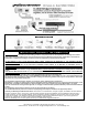
Model TSPBIW
A
The POWER OUTLET and POWER INLET plates can be installed either vertically or horizontally
~ Determine location on wall/ceiling between framing studs, with a stud-finder.
~ Trace a cut-line with the supplied cardboard template.
~ Level for proper alignment. ~ Cut around outside of line, using a drywall saw or utility knife.
~ CAUTION: DO NOT CUT AREA BETWEEN LARGE AND SMALL OPENING
~ Route In-Wall PowerWire within wall/ceiling between the two larger cutouts.
~ Route Audio/Video Cables within wall/ceiling between the two smaller cutouts.
~ Using a screwdriver, bend one tab OUT on the backside of the WHITE box.
~ Insert PowerWire. Allow 4 inches to stick out from the edge of the box, strip off 3 inches
of the outer sheath of the power-wire.
~ Insert the WHITE box into the wall opening. ~ Screw in the 2 silver screws to open the
wall-wings to secure the boxes to the wallboard. ~ Use a level for proper alignment.
POWER OUTLET ~ (Female Receptacle)
(A) Using the tip of needle-nose pliers or the “bend hole” on a wire stripper, bend the
wire-end into a “J” shaped hook.
(B) Hook the wire-end on the right “clockwise” side of the screw as shown.
Tighten the screws to each wire. ~ Check for proper wiring connections as labeled.
POWER INLET ~ (Male Plug)
*DO NOT BEND OR “J” THE END OF THE WIRES.
(C) Insert each of the three wires straight into the WIRE INSERT HOLES located on
end of the INLET. Each hole aligns with a colored screw around the sides.
Tighten the screws to each wire. ~ Check for proper wiring connections as labeled.
Push excess electrical wire back through rear opening of the WHITE box.
Secure both wall plates with color - matched screws.
POWER INLET
~ Plug “female” end of the POWER CORD, onto the “male” plug of the POWER INLET.
~ Plug “male” plug of the POWER CORD into the existing A/C outlet or power surge protector.
THE SYSTEM IS NOW POWERED
NOTE: If the supplied POWER CORD is not long enough, DO NOT EXTEND THE SUPPLIED CORD with another
extension cord. Must use 3 prong-grounded, UL LISTED extension cord. DO NOT EXCEED 15 FEET IN LENGTH.
L
E
V
E
L
POWER OUTLET
OPTIONAL: CHECK FOR PROPER WIRING CONNECTIONS WITH AN OUTLET-TESTER
The HDTV is now ready to plug in, enjoy your wall-mounted system!
B
ETL LISTED CONFORMS TO UL STD 514C
CERTIFIED TO CAN/CSA STD C22.2 NO. 42.1
C
The manufacturer, intend to make this manual accurate and complete. However, no claim that the information contained herein covers all details, conditions, or variations. Nor does it
provide for every possible contingency in connection with the installation or use of this product. The information contained in this document is subject to change without notice or obligation
of any kind. Manufacturer makes no representation of specific warranty beyond the Limited Warranty, expressed or implied, regarding the information contained herein.
©2007-11 Ver.4.811