
Use and Care Guide


9
minimum dimension of rectangular air ducts cannot be less
than three inches.
The size of each of the two openings is determined by the
method in which the air is to be provided. Refer to Table
4 to calculate the minimum free area for each opening.
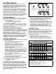
Figures 5, 6, and 7 are typical examples of each method.
Louvers and Grilles
In calculating free area for ventilation and combustion
air supply openings, consideration must be given to the
blocking effect of protection louvers, grilles, and screens.
These devices can reduce airflow, which in turn may
require larger openings to achieve the required minimum
free area. Screens must not be smaller than 1/4” mesh. If
the free area through a particular design of louver or grille
is known, it should be used in calculating the specified
free area of the opening. If the design and free area are
not known, it can be assumed that most wood louvers will
allow 20 - 25% of free area while metal louvers and grilles
will allow 60 - 75% of free area.
Louvers and grilles must be locked open or interconnected
with the equipment so that they are opened automatically
during equipment operation.
Keep louvers and grilles clean and free of debris or other
obstructions.
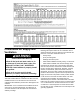
Table 4
Minimum Free Area of Permanent Openings for
Ventilation and Combustion Air Supply -
All Air from Outdoors Only
Based on the total BTUH input rating for all gas utilizing equipment
within the confined space.
Opening Source
Minimum Free
Area Per Opening
(Sq. In.)
Reference
Drawing
Directed to Outdoors* 1 sq. in. per 4000 BTUH Figure 5
Vertical Ducts 1 sq. in. per 4000 BTUH Figure 6
Horizontal Ducts 1 sq. in. per 2000 BTUH Figure 7
Single Opening 1 sq. in. per 3000 BTUH Figure 7A
Example: A water heater with an input rating of 50,000 BTUH using
horizontal ducts would require each opening to have a minimum free
area of 25 square inches.
Minimum free area = 50,000 BTUH x 1 sq. in. / 2000 BTUH = 25 sq. in.
*These openings connect directly with the outdoors
through a ventilated attic, a ventilated crawl space, or
through an outside wall.
Consult the local codes of your area for specific ventilation
and combustion air requirements.
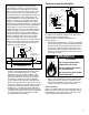
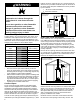
Figure 5
All Air From Outdoors: Inlet Air
From Ventilated Crawl Space/
Outlet Air to Vented Attic
Gable Vent
to Outdoors
Install Above
Insulation
Confined
Space
Outlet Air
to the Attic
1 sq. in. per
4000 BTUH
Inlet Air
from the
Crawl Space
Alternative
Air Inlet
1 sq. in. per
4000 BTUH
Open
Foundation
Vent
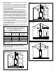
Figure 7
All Air From Outdoors
Using Horizontal Ducts
Gable Vent
to Outdoors
Install Above
Insulation
Confined
Space
Figure 6
All Air from Outdoors
Through Ventilated Attic
Outlet Air
to the Attic
1 sq. in. per
4000 BTUH
Inlet Air Duct
1 sq. in. per
4000 BTUH
12” Max.
Confined
Space
1 sq. in. per
2000 BTUH
Outlet
Outdoor
Air Ducts
Inlet
1 sq. in. per
2000 BTUH
Figure 7A
All Air From Outdoors
Using a Single Permanent Opening
Confined
Space
1 sq. in. per
3000 BTUH
Alternative
Opening
Location