
Installation Guide

10
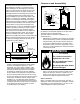
Vent Pipe System
This water heater must be properly vented for removal
of exhaust gases to the outside atmosphere. Correct
installation of the vent pipe system is mandatory for the
safe and efficient operation of this water heater and is an
important factor in the life of the unit.
The vent pipe must be installed in accordance with state
and local codes, or in the absence of such, the National
Fuel Gas Code, NFPA 54, ANSI Z223.1-current edition.
IMPORTANT: Check to make sure the vent pipe is not
blocked in any way. NOTE: Do not common vent this
water heater with any other appliance. Do not install in the
same chase or chimney with a metal or high-temperature
plastic from another gas or fuel burning appliance.
Vent Pipe Material
The following plastic materials may be used for both the
combustion air inlet and exhaust outlet piping subject to
state and local codes:
• 2 or 3 inch Schedule 40 PVC or ABS
• 2 or 3 inch Schedule 40 or 80 CPVC
• DWV Pipe is acceptable
NOTE: Use only solid (not foam core) piping. Plastic pipe
and fittings are available through most plumbing suppliers.
Always check the marking on the pipe to make sure you
are using the correct material.
Vent Pipe Connection to Blower
A 3”x2” condensate drain coupler is supplied with every 40-42K
BTU model to connect either 2” or 3” venting to the blower. A
3” condensate drain coupler is supplied with every 50-60K BTU
model to connect 3” venting to the blower.
IMPORTANT: These connections must be properly sealed to
prevent the leakage of the products of combustion into the
living area. If needed 3”x2” & 3” condensate drain couplers are
available through the Parts Department for new installations or
retrofits where condensate may run back to the blower.
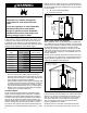
Vent Pipe Installation
The following guidelines should be followed when installing
the exhaust outlet piping:
• Venting should be as direct as possible with a
minimum number of pipe fittings.
• Vent diameter must not be reduced unless
specifically noted in the installation instructions.
• Support all horizontal pipe runs every four feet
and all vertical pipe runs every six feet or
according to local codes.
• Vents run through unconditioned spaces where below
freezing temperatures are expected should be properly
insulated to prevent freezing. For horizontal runs,
wrap the vent pipe with self-regulating 3 or 5 watt heat
tape. The heat tape must be U.L. listed and installed
per the manufacturer’s instructions.
• Do not connect this venting system with an existing
vent or chimney.
• Do not common vent with the vent pipe of
any other water heater or appliance.
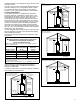
The exhaust outlet piping and termination may be installed
in one of the following type terminations:
1. Standard Horizontal
2. Vertical
All pipe, fittings, pipe cement, primers and procedures
must conform to American National Standard Institute and
American Society for Testing and Materials (ANSI/ASTM)
standards in the United States. This water heater has been
design certified by CSA International for use with the listed
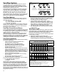
plastic vent pipe material. IMPORTANT: Do not use vent
elbows in this vent pipe installation (see figure 8). All joints in
the outlet piping must be properly cemented. Size and cut all
piping before cementing.
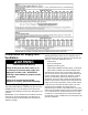
Table 5 - Maximum Allowable Length in Feet of
Exhaust Pipe - (42K BTU/Hr models only)
Pipe
Size
(in)
Number of 90° Elbows (medium or long sweep only)
Termination
Options
0123456
2 40 35 30 25 20 15 10 Std. Horizontal
2 40 35 30 25 20 15 10 Vertical
3 120 115 110 105 100 95 90 Std. Horizontal
3 120 115 110 105 100 95 90 Vertical
Table 6 - Maximum Allowable Length in Feet of
Exhaust Pipe - (50K/60K BTU/Hr models only)
Pipe
Size
(in)
Number of 90° Elbows (medium or long sweep only)
Termination
Options
0123456
2 N/A Std. Horizontal
2 N/A Vertical
3 65 60 55 50 45 40 35 Std. Horizontal
3 65 60 55 50 45 40 35 Vertical
Notes:
1. N/A - Not Applicable
2. The above maximum lengths are for outlet pipe systems.
3. Maximum of 6 elbows may be used. Use only medium or long
sweep elbows. See figure 8 for details.
4. Two 45° elbows are considered equivalent to one 90° elbow.
5. Minimum length is 3 foot with 1 elbow.
6. Use schedule 40 or 80 CPVC, 40 ABS, or 40 PVC pipe and fittings.
1. Cut the pipe end square and remove all ragged edges
and burrs. Make sure the inside of the pipe is clean
and free of cuttings and loose dirt. Chamfer the end
and apply primer to the fitting and pipe.
2. Using a suitable grade of pipe cement, apply a
moderate, even coat inside the fitting. Apply a liberal
amount of cement to the outside of the pipe to socket
depth. NOTE: It is important to select the proper pipe
cement for the type plastic pipe being used.
3. Assemble the parts quickly while the cement is still
wet. Twist the pipe 1/4 turn during insertion and hold
for 30 seconds.
Vent Pipe Length
Size the exhaust outlet as specified in Tables 5 & 6 below.
These tables list the maximum allowable length in feet of
the exhaust outlet pipe as related to the number of required
elbows and the termination. The specified maximum
lengths are for exhaust pipe systems. Minimum pipe length
is 3 feet with one elbow.
1. Determine termination type and pipe size.
2. Determine number of elbows in exhaust pipe (Do not
include elbows in the termination.) Corresponding
number indicates the maximum length of exhaust pipe.
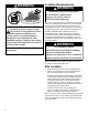
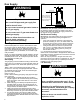
CORRECT FITTINGS
Mesh Metal
Rodent Screen
90° Medium
Sweep Elbow
45° Sweep
Elbow
90° Long
Sweep Elbow
INCORRECT FITTINGS
90° Vent
Elbow
45° Vent
Elbow
Tee Connector
Figure 8
Correct and Incorrect
Pipe Fittings