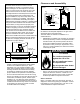
Flammable Vapor Ignition Resistant Compliant Power Vented Gas Water Heater Installation Instructions and Use & Care Guide WARNING: If the information in these instructions is not followed exactly, a fire or explosion may result causing property damage, personal injury or death. Do not store or use gasoline or other flammable vapors and liquids in the vicinity of this or any other appliance.
WATER HEATER SAFETY This is the safety alert symbol. It is used to alert you to potential personal injury hazards. Obey all safety messages that follow this symbol to avoid possible injury or death. DANGER DANGER indicates an imminently hazardous situation which, if not avoided, could result in death or injury. WARNING WARNING indicates a potentially hazardous situation which, if not avoided, could result in death or injury.
INSTALLING YOUR GAS WATER HEATER Consumer Information This water heater must be installed according to all local and state codes or, in the absence of local and state codes, the “National Fuel Gas Code”, ANSI Z223.1(NFPA 54)-current edition. WARNING Excessive Weight Hazard CSA America, Inc. 8501 East Pleasant Valley Road Cleveland, OH 44131 Use two or more people to move and install water heater.
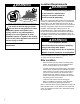
WARNING Location Requirements WARNING Carbon Monoxide Poisoning Hazard Do not install in a mobile home. Doing so can result in death or carbon monoxide poisoning. FLAMMABLES Flammable Vapors FIRE AND EXPLOSION HAZARD Can result in serious injury or death Do not store or use gasoline or other flammable vapors and liquids in the vicinity of this or any other appliance.
CAUTION - PROPERTY DAMAGE HAZARD The water heater should be located in an area where leakage of the tank or connections will not result in damage to the area adjacent to the water heater or to lower floors of the structure. Due to the normal corrosive action of the water, the tank will eventually leak after an extended period of time. Also any external plumbing leak, including those from improper installation, may cause early failure of the tank due to corrosion if not repaired.
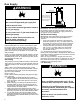
Gas Supply Figure 2 Gas Piping WARNING Manual gas shut-off valve Explosion Hazard Install a readily accessible manual shut-off valve in the gas supply line as recommended by the local utility. Use a new CSA approved gas supply line. Install a shut-off valve. Do not connect a natural gas water heater to an L.P. gas supply. Do not connect an L.P. gas water heater to a natural gas supply. Failure to follow these instructions can result in death, explosion, or carbon monoxide poisoning.
Combustion Air Supply and Ventilation WARNING Carbon Monoxide Warning Follow all the local and state codes or, in the absence of local and state codes, the “National Fuel Gas Code”, ANSI Z223.1 (NFPA 54)- latest edition to properly install vent system. Failure to do so can result in death, explosion, or carbon monoxide poisoning.
heaters, furnaces, clothes dryers, etc.) and the method by which the air is provided. The BTUH input can be found on the water heater data plate. Additional air can be provided by two methods: 1. All air from inside the building. 2. All air from outdoors. WARNING Fire and Explosion Hazard Combustion air is drawn through the bi-directional air vent above the water heater. Do not store gasoline or other flammable substances above this water heater.
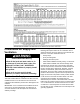
minimum dimension of rectangular air ducts cannot be less than three inches. The size of each of the two openings is determined by the method in which the air is to be provided. Refer to Table 4 to calculate the minimum free area for each opening. Figures 5, 6, and 7 are typical examples of each method. Louvers and Grilles In calculating free area for ventilation and combustion air supply openings, consideration must be given to the blocking effect of protection louvers, grilles, and screens.
Vent Pipe System This water heater must be properly vented for removal of exhaust gases to the outside atmosphere. Correct installation of the vent pipe system is mandatory for the safe and efficient operation of this water heater and is an important factor in the life of the unit. The vent pipe must be installed in accordance with state and local codes, or in the absence of such, the National Fuel Gas Code, NFPA 54, ANSI Z223.1-current edition.
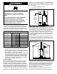
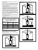
Vent Termination Locations The exhaust outlet must be installed with the following minimum clearances (see figure 9): In addition to maintaining the minimum clearances , the vent should terminate according to the following guidelines: 1. Do not expose any reducers or bushings to outdoor ambient temperatures. • Twelve inches above grade or maximum anticipated snow level. • Twelve inch minimum clearance on top or four foot clearance below or to the side of door or window that may be open.
OUTLET VENT TERMINATIONS Standard Horizontal Termination Vertical Termination The standard horizontal exhaust outlet termination is a 2 inch or 3 inch pipe which terminates 12 inches from the outside wall (see figure 10). To prevent potential condensate from collecting in the venting system slope the vent at a downward pitch of 1/8” per 5ft. away from the water heater. Install the correct size coupling at the outside wall on the exhaust to prevent the termination from being pushed inward.
WATER SYSTEM PIPING Piping Installation Figure 12 Typical water piping installation Piping, fittings, and valves should be installed according to the installation drawing (Figure 12). If the indoor installation area is subject to freezing temperatures, the water piping must be protected by insulation. In a closed system use a thermal expansion tank Cold Water Inlet Valve Hot Water Outlet Cold Water Supply to Fixture Water supply pressure should not exceed 80psi.
Closed System/Thermal Expansion CAUTION - PROPERTY DAMAGE HAZARD Periodic discharge of the temperature and pressure relief valve may be due to thermal expansion in a closed water supply system. The water utility supply meter may contain a check valve, backflow preventer or water pressure reducing valve. This will create a closed water system. During the heating cycle of the water heater, the water expands causing pressure inside the water heater to increase.
The Temperature and Pressure Relief Valve: • Shall not be in contact with any electrical part. • Shall be connected to an adequate discharge line. • Shall not be rated higher than the working pressure shown on the data plate of the water heater. The Discharge Line: • Shall not be smaller than the pipe size of the relief valve or have any reducing coupling installed in the discharge line.
INSTALLATION CHECKLIST Water Heater Location • Acceptable size, length, and number of elbows on exhaust outlet pipe. • Centrally located with the water piping system. Located as close to the gas piping and vent pipe system as possible. • • Located indoors and in a vertical position. Protected from freezing temperatures. Installed in accordance with prevailing provisions of local codes, or in the absence of such, National Fuel Gas Code, NFPA 54, ANSI Z223.1-Current edition.
OPERATING YOUR WATER HEATER Lighting Instructions WARNING Read and understand these directions thoroughly before attempting to operate the water heater. Make sure the tank is completely filled with water before operating the water heater. Check the data plate near the gas control valve/thermostat for the correct gas. Do not use this water heater with any gas other than the one listed on the data plate. If you have any questions or doubts, consult your gas supplier or gas utility company.
L.P.G. (Bottled Propane) Models Liquefied petroleum gas is over 50% heavier than air and in the occurrence of a leak in the system, the gas will settle at floor level. Basements, crawl spaces, skirted areas under mobile homes (even when ventilated), closets and areas below ground level will serve as pockets for the accumulation of gas. Before lighting an L.P. gas water heater, smell all around the appliance at floor level. If you smell gas, follow the instructions as given in the warning on the front page.
30 seconds if no further buttons are pressed. After 30 seconds the control will go back to “Sleep” mode. 2. Release both of the temperature adjustment buttons. A. To decrease the temperature press and release the “COOLER” button until the desired setting is reached. B. To increase the temperature press and release the “HOTTER” button until the desired setting is reached. NOTE: Holding down the button will not continue to lower or raise the temperature setting.
MAINTENANCE OF YOUR WATER HEATER Draining and Flushing It is recommended that the tank be drained and flushed every 6 months to remove sediment which may build up during operation. The water heater should be drained if being shut down during freezing temperatures. To drain the tank, perform the following steps: 1. Turn off the gas to the water heater at the manual gas shut-off valve. 2. Turn off the electrical supply to the water heater. 3. Close the cold water inlet valve. 4.
Replacement Parts Replacement parts may be ordered through your plumber or the local distributor. Parts will be shipped at prevailing prices and billed accordingly. When ordering replacement parts, always have the following information ready: 1. model, serial, and product number 2. type of gas 1. Take off the burner by removing the two (2) screws located underneath the burner. 2. Check the burner to see if it is dirty or clogged. The burner may be cleaned with soap and hot water. See Figure 21.
WARNING Explosion Hazard Tighten both manifold door screws securely. Remove any fiberglass between gasket and combustion chamber. Replace viewport if glass is missing or damaged. Replace two piece wire connector if missing or removed. Replace door gasket if damaged. Failure to follow these instructions can result in death, explosion, or fire. Replacing the Manifold Assembly 1. Check the door gasket for damage or imbedded debris prior to installation. 2.
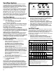
TROUBLESHOOTING LED STATUS PROBLEM SOLUTION An open earth ground circuit to the ignition system. 1. Check that the earth ground connection is properly connected. 2. Check that the earth ground conductor on the water heater is properly connected. Wiring error or a high resistance to earth ground. 1. Check for proper connection of line neutral and hot wires. 2. Check that the water heater is securely connected to earth ground. Pressure switch remained closed longer than 5 1.
TROUBLESHOOTING PROBLEM NO HOT WATER NOT ENOUGH HOT WATER VENT PIPE TOO HOT (ABOVE 170°F) YELLOW FLAME CONDENSATION WATER LEAKS LEAKING T&P HOT WATER ODORS (See ANODE ROD/WATER ODOR, Section) WATER TOO HOT WATER HEATER SOUNDS SIZZLING-RUMBLING SOOTING HEATER LIGHTS BUT GOES OUT IN 4-5 SECONDS 24 cont. CAUSE Blower will not run. A) Blower unplugged. B) No power at outlet. C) Thermostat defective. D) High limit control circuit open. E) Blower motor defective. F) Pressure switch defective.
REPAIR PARTS ILLUSTRATION When ordering repair parts always give the following information: 1. 2. 3. 4. Model, serial and product number Type of gas Item number Parts description 1 Repair Parts List Item No.
Listed Parts Kits and Illustrations Item 11: Item 12: Item 13: Item 14: Item 15: Item 16: Item 17: Item 18: Flame Sense/Hot Surface Igniter Assembly. Burner (Natural Gas) Burner (L.P. Gas) Manifold door assembly which contains the manifold tube, gasket, manifold door, two piece wire connector with retainer clip, and flame sense/hot surface igniter assembly.