Owner’s Manual M11965B.5 ITEM NUMBER: 11965 SERIAL NUMBER: _______________ Instructions for Assembly, Testing, Operation, Servicing, & Storage Log Splitter: Outdoor hydraulic powered machine that splits wood logs. WARNING READ and UNDERSTAND this manual completely before using log splitter. All operators of this equipment must read and completely understand all safety information, operating instructions, maintenance and storage instructions.
Hazard Signal Word Definitions 2
Table of Contents Hazard Signal Word Definitions .............................................................................................................. 2 Table of Contents ..................................................................................................................................... 3 About Your Log Splitter........................................................................................................................... 4 Safety Label Locations ........................
About Your Log Splitter Thank you for purchasing your Powerhorse log splitter! About Your Log Splitter: This log splitter is a machine designed to split wood logs using a hydraulically powered moving wedge. The log splitter is connected to and powered by your tractor’s hydraulic system. This log splitter is designed to split logs lengthwise with the grain only. This log splitter model is capable of splitting logs up to 25” long and 14” in diameter.
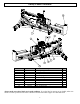
Safety Label Locations Reference # Part Number 1 2 3 4 5 6 7 8 9 10 778717 787944 778609 777891 777889 778610 777887 778597 791352 778714 Description Decal, Log Stripper Decal, Pinch Point Decal, Split Control Decal, Escaping Fluid Decal, Stuck Log Decal, Log Splitter Warning Decal, Operation Instructions Decal, Horizontal Lock Decal, Connecting/Driving Decal, Vertical Lock Qty 2 1 1 1 1 1 1 1 1 1 Always make sure safety labels are in good condition.
from air intakes. NEVER use inside homes, garages, or sheds. EVEN IF you run a fan or open doors and windows. See product manual for more details. WARNING 1 Safety Label Locations 2 ©2005 Northern Tool + Equipment Co. 1-800-270-0810 PN 39259 ©2005 Northern Tool + Equipment Co. 1-800-270-0810 POISONOUS GAS This product's use gives off carbon monoxide, an odorless gas that can kill you. ONLY use outdoors and away from air intakes. NEVER use inside homes, garages, or sheds.
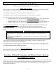
Machine Component Identification Ref 1 2 3 4 5 6 7 8 Description Category 1 Lower Pin Category 2 Lower Pin Category 1 Upper Pin Category 2 Upper Pin Cylinder Hydraulic Return Port Valve Wedge Ref 9 10 11 12 13 14 15 16 7 Description Log Cradle Vertical Lock Pin Manual Tube Beam Endplate Stripper Horizontal Lock Hydraulic Supply Port
Initial Set-up IMPORTANT! Carefully read and follow all instruction for initial assembly and set-up of this log splitter. Failure to properly assembly and set up this equipment could result in serious injury to the user or bystanders, or cause equipment damage. 1. Inspect Log Splitter Components Closely inspect all log splitter components. 2. Lubricate Beam Apply grease to beam. This will help prevent wear between the wedge and beam.
Connecting to Tractor & Transporting to Job Site WARNING The log splitter must be correctly mounted and then attached to the tractor hydraulic system for safe operation. Follow the instructions below for safety mounting and connecting the log splitter. 1. Read instructions Review your tractor manual or check with your dealer for instructions and safety information about how to properly connect the log splitter to your tractor’s hydraulics.
Connecting to Tractor & Transporting to Job Site 4. Measure & cut hydraulic hoses to correct length. Measure & cut hydraulic hoses to the appropriate length for connecting log splitter to tractor hydraulics: a. You will need to supply two 1/2” hydraulic hoses rated for 3000 PSI with male, 1/2” NPT threaded ends. b. Measure the distance from your tractor’s hydraulic supply port to the supply inlet port on the log splitter’s control valve.
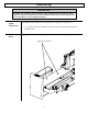
Connecting to Tractor & Transporting to Job Site Tractor return hose Tractor supply hose 5. Connect hydraulic hoses 6. Add hydraulic oil to reservoir Connect the hydraulic hoses: a. Connect one hose from the tractor’s hydraulic supply port to the supply inlet port on the log splitter’s control valve. b. Connect the second hose from the tractor’s return port to the connection at the return outlet port on the log splitter’s control valve. c. Check to be sure that all fittings are tight.
Connecting to Tractor & Transporting to Job Site 7. Hydraulic components Check the hydraulic components carefully: 1. Visually inspect all hoses and clamps/fittings for cracks, fraying, kinks, or other damage. 2. Check all components for oily residue, which may indicate a leak. Do NOT operate the log splitter if there is any indication of damage or oily residue. Small leaks in hydraulic lines can cause severe injuries and can also be an indication of catastrophic failure in the near future.
Connecting to Tractor & Transporting to Job Site Towing: 1. Read instructions Review towing safety instructions in your vehicle manual. 2. Drive to desired location Drive tractor and log splitter carefully to desired work site. (See instructions on pg.15 on selecting an appropriate work site) Important safety instructions: • • • • • • • • 3. Engage parking break Read tractor instructions.
Before Each Use – Work Site Selection and Set Up Step One: Inspect and maintain log splitter before each use If the log splitter has been used previously, it must be inspected and maintained BEFORE EACH SUBSEQUENT USE. WARNING ALWAYS shut off the tractor, disconnect hydraulic lines, and relieve system pressure before inspecting, cleaning, adjusting, or repairing the splitter. Relieve system pressure by moving Split Control Lever back and forth several times.
Before Each Use – Work Site Selection and Set Up • NEVER adjust the pressure setting of the valve. • If injured by escaping fluid, no matter how small the wound is, see a doctor at once. A typical injection injury may be a small puncture wound that does not look serious. However, severe infection or reaction can result if proper medical treatment is not administered immediately by a doctor who is familiar with injection injuries. 6.
Splitting Operation WARNING Before starting this log splitter, review the following instructions and safety information for safe operation of the log splitter. Failure to follow these rules may result in serious injury to the operator or bystanders from moving parts that crush, cut, or entangle from flying objects, burns, fire, falling or tripping, or from carbon monoxide poisoning. • • • • • • • • • • • • • • • • • General safety information: Read manual.
Splitting Operation 1. Put on protective clothing / gear Wear the following protective clothing and safety gear: 2. Engage parking brake Secure log splitter from unintended movement—make sure the tractor’s parking brake is engaged before operating the log splitter. 1. Eye protection. Always wear safety glasses or goggles when operating the machine. Pieces of log may fly out and serious eye injury can occur. 2. Boots. Falling logs can crush feet.
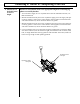
Splitting Operation b) Set to Vertical position Vertical Splitting Position Pull out horizontal lock latch rod, grasp and lift beam until it rotates into vertical position. Vertical Lock WARNING: Crush hazard. The beam is heavy – do not let it just drop. It could crush fingers or cause damage to the splitter. 1. Remove lynch pin and vertical lock pin and pivot beam to vertical position. 2. Lock in vertical position using vertical lock pin and lynch pin through the vertical lock. 3.
Splitting Operation 4. Load log Load log onto beam with a cut end against the endplate – positioned for a lengthwise cut. Notes: a) The log splitter is designed only for cutting lengthwise with the grain, NOT for cutting across the grain. b) This log splitter is designed for cutting logs only up to a maximum of 14” in diameter and 25” long. Larger diameter logs could get stuck on the wedge and longer logs will not fit on the beam.
Splitting Operation 5. Extend wedge Move Split Control Lever toward endplate to extend wedge and split log. SPLIT CONTROL LEVER OPERATION Important safety instructions: • Operator position. ALWAYS operate the log splitter from the manufacturer’s indicated OPERATOR POSITION. (See diagram above.) Other positions are unsafe because they can increase the risk of injury from crushing, cutting, flying objects, or burns. • Remove hands. Remove both hands from log before activating Split Control Lever.
Splitting Operation WARNING: NEVER attempt to remove a stuck log by: • Modifying the splitter. • Adding attachments to the splitter. Personal injury could result from log or metal pieces flying out at high speed toward the operator or bystanders, or the splitter could become damaged. 8. Return wedge Move Split Control Lever away from end plate to return wedge.
Storage Follow the instructions below for storing your log splitter between uses. 1. Retract wedge Retract the wedge completely to keep the rod protected from corrosion. 2. Wipe with oily rag Wipe the beam and wedge with an oily rag to prevent corrosion. 3. Splitter storage location Store the log splitter in a location away from corrosive material. NOTE: Do not store the log splitter near fertilizer or any other corrosive material.
Periodic Maintenance In addition to the maintenance performed with each use, periodic maintenance should also be performed according to the following schedule. WARNING ALWAYS shut off the tractor engine and relieve system pressure before cleaning, adjusting, or repairing the splitter. Relieve system pressure by moving Split Control Lever back and forth several times. IMPORTANT: If a part needs replacement only use parts that meet the manufacturer’s specifications.
Troubleshooting WARNING Before troubleshooting or attempting to service, read the following safety instructions to avoid serious injury to the operator or bystanders from moving parts that can crush or cut, burns, fire or explosion, or escaping high pressure hydraulic fluid. Important Safety Instructions: 1. Tractor off. Always make sure the tractor engine is off before cleaning, repairing or adjusting the splitter, except as recommended by the manufacturer. 2. Hydraulic safety.
Specifications Item # …………………….. Tonnage…………………… Max Pressure……………… Max Flow…………………. Hydraulic Cylinder Bore…. Hydraulic Cylinder Stroke .. Maximum Log Diameter…. Maximum Log Length ........ Hydraulic Fluid Type……... Hydraulic Oil Capacity…… Control Valve Type………. Overall Dimensions ............ Dry Weight………………..
Parts Breakdown – Exploded View 11965 – Rev B.
Parts Breakdown – Exploded View 11965 – Rev B.5 Item 1 2 3 4 5 6 7 8 9 10 11 12 13 14 15 16 17 18 19 20 21 22 23 24 25 26 27 28 29 30 31 32 33 34 35 36 37 Part No.
Summary of Important Safety Information for Operation WARNING Carefully read and make sure you understand the following safety information before using the log splitter. Improper use or maintenance of the log splitter can result in serious injury to the operator or bystanders from moving parts that can crush or cut, flying objects, burns, fire or explosion, escaping high pressure hydraulic fluid, or carbon monoxide poisoning. Introduction • • • Read Manual.
Summary of Important Safety Information for Operation Safety in Transporting to Job Site • • • • • • • • • • Read tractor instructions. Review safety instructions in your tractor manual with regard to driving with 3-point hitch mounted equipment attached. Securely attached. Be sure the log splitter is securely attached before transporting. Added length. Be aware of the added length of the splitter. Reduced road stability.
Summary of Important Safety Information for Operation • Hydraulic system. Check the hydraulic system (hoses, tubing, clamps/fittings, pump, and cylinder) carefully before each use. Do not operate the log splitter with frayed, kinked, cracked or damaged hydraulic hoses, fittings, or tubing, or if oily residue is observed on any of the components. High fluid pressures and temperatures are developed in the log splitter.
Summary of Important Safety Information for Operation • • • • • • • • Know how to stop. Be thoroughly familiar with all controls and with the proper use of the equipment. Know how to stop the log splitter and relieve system pressures quickly if needed. Daylight only. Only use the log splitter in daylight so you can see what you are doing. Smoking / sparks. Never smoke while operating the log splitter, and never operate near sources of sparks or flames. Unattended.
Summary of Important Safety Information for Operation o o o o o Split log pile. Move each log away from log splitter after it is split. Split logs left near the log splitter are a trip hazard. Remove hands. Remove both hands from log before activating Split Control Lever. Hand activate. Use only your hand to operate the Split Control Lever. Never use any other body part, or a rope, cable, or other remote device to actuate the control. Returning wedge.
Assembly Instructions Closely inspect all log splitter components. If you have missing or damaged components, please contact Powerhorse Product Support at 1-866-443-2576. CAUTION Heavy lifting required. Some of the components in these assembly instructions are heavy and cannot be lifted by one person safely. Please plan on assembling this product when another person can be available to help out. CAUTION Remove the cylinder from the beam assembly before assembling.
Assembly Instructions Bracket Assembly Contents: Lower Pivot Assembly Horizontal Brackets Vertical Brackets Side Brackets Manual Bag Contents: Owner’s Manual Hydraulic Valve 34
Assembly Instructions Fastener Bag Contents: Actual fastener size shown in the assembly steps Horizontal Latch to Beam M12-1.75 X 35 HHSF Part # 82551 Qty: 2 Lynch Pin Part # 39159 Qty: 5 Cotter Pin Part # 778674 Qty: 1 Cradles to Beam M8-1.25 X 30 HHSF Part # 82545 Qty: 4 Vertical Pin Part # 791183 Qty: 1 Bracket Assembly M10-1.5 X 35 HHSF Part # 82535 Qty: 8 Tow Bar to Bracket M10-1.5 X 10⁵ HHSF Part # 82558 Qty: 2 Pivot Pin Part # 790472 Qty: 1 Log Cradles to Beam M8-1.
Assembly Instructions Step 1 – Beam Assembly Tools Needed • Rotate cylinder 180° and place cylinder in trunnion mounts on beam (see Step 2 image for the correct orientation) Rotate Cylinder 180° Trunnion Mount Cylinder 36
Assembly Instructions Step 2 – Beam Assembly • • • • Support the end of the cylinder until connected to the wedge Ensure the ports on the cylinder are facing up Remove the existing bolt and nut from the wedge Slide wedge towards the cylinder rod Tools Needed • 22mm Wrench (2 needed) Fasteners Needed from Parts Bag: Cylinder Ports Cylinder Ports Wedge Cylinder Rod Remove Existing Nut for Use in Step 3 37 Remove Existing Bolt for Use in Step 3
Assembly Instructions Step 3 – Beam Assembly Tools Needed • Align hole in wedge with the hole in the cylinder rod • Install the existing bolt and nut to connect the wedge to the cylinder. • Torque to 114 ft.-lb.
Assembly Instructions Step 4 – Log Stripper Assembly Tools Needed • Align holes in the log stripper with the holes in the trunnion mount • Attach the log stripper to beam using the nuts and bolts from Parts Bag. Torque to 21 ft.-lb. • Stand assembled beam onto the end plate in the vertical position and move to the side. • 13mm Wrench • Torque Wrench Fasteners Needed from Parts Bag: Log Stripper to Beam M8-1.25 X 25mm Bolt Qty: 6 Log Stripper to Beam M8-1.
Assembly Instructions Step 5 – Tow Bar Assembly Tools Needed • Align holes on the tow bar to the lower pivot assembly. • Install (4) bolts and (4) nuts and hand tighten to allow for adjustment. • Fasteners will be torqued to 41 ft.-lb. in Step 7. • 15mm Wrench • Torque Wrench Fasteners Needed from Parts Bag: Bracket Assembly M10-1.5 X 25mm Bolt Qty: 4 Bracket Assembly M10-1.
Assembly Instructions Step 6 – Tow Bar Assembly Tools Needed • Align holes in mast with the holes in the lower pivot assembly. • Install (4) bolts and (4) nuts and hand tighten to allow for adjustment. • Fasteners will be torqued to 41 ft.-lb. in Step 7. • 15mm Wrench • Torque Wrench Fasteners Needed from Parts Bag: Bracket Assembly M10-1.5 X 25mm Bolt Qty: 4 Bracket Assembly M10-1.
Assembly Instructions Step 7 – Tow Bar Assembly Tools Needed • Align horizontal, vertical and side brackets as shown below. Hand • • 15mm Wrench • 16mm Wrench • Torque Wrench tighten bolts initially to allow for movement during bracket assembly. Once all pieces are assembled using bolts and nuts from parts bag, torque to 41 ft.-lb.
Assembly Instructions Step 8 – Tow Bar Assembly • Place tow bar assembly on flat surface and orient as shown below. Make sure a helper holds onto the top of the beam assembly during the remainder of this step. The beam is very heavy and dangerous if it tips over. • Align the pivot hole on the beam assembly to the pivot hole on the tow bar assembly and insert pivot pin. • Insert cotter pin through hole in pivot pin. Use pliers to spread and bend prongs in opposite directions to secure.
Assembly Instructions Step 9 – Tow Bar Assembly Tools Needed • Insert vertical pin through vertical pin hole in tow bar assembly and • beam assembly. Insert lynch pin through hole in vertical pin to secure.
Assembly Instructions Step 10 – Horizontal Latch Bracket Assembly • Install the horizontal latch bracket to the beam assembly in orientation • • • • • shown below, using (2) bolts and (2) nuts. Torque to 71 ft.-lb. Remove lynch pin from vertical pin and pull out vertical pin. Pivot beam to horizontal position, ensure horizontal latch pin locks into the horizontal latch bracket. Note: If latch pin does not properly lock into horizontal latch bracket, loosen bolts and adjust until latch pin locks.
Assembly Instructions Step 11 – Log Cradle Assembly Tools Needed • Install (2) bolts and (2) nut into the bottom holes of the beam. • Using the slots in the bottom of each log cradle arm, rest the log cradle arms on the installed bolts and nuts. • Install the remaining (2) bolts and (2) nuts into the top holes of the beam and log cradle arms. • Torque to 21 ft.-lb. Fasteners Needed from Parts Bag: Cradles to Beam M8-1.25 x 30mm Bolt Qty: 4 Cradles Cradles to Beam M8-1.
Assembly Instructions Step 12 – Top Link Pins Tools Needed • Install Category 1 and Category 2 top link pins into their respective holes. • Insert (2) lynch pins into top link pins to secure. • Insert remaining (2) lynch pins into lower link pins according to which Category Link you have. Fasteners Needed from Parts Bag: Cat. 2 Top Link Pin Part #: 791139 Qty: 1 Cat. 1 Top Link Pin Part #: 791138 Qty: 1 Cat. 2 Top Link Pin Lynch Pin Cat. 1 Top Link Pin Lynch Pin Cat. 2 Hole Cat.
Assembly Instructions Step 13 – Control Valve Tools Needed • Slide control valve handle into the clevis slots on the control valve. • Align holes in handle with clevis holes. • Insert the supplied pins through holes and secure with supplied bridge clips.
Assembly Instructions Step 14 -Fittings Tools Needed • Remove plug from cylinder port and discard • Lubricate O-ring and threads on fitting with clean oil • Orientate (1) Valve Fitting so that nut/washer/O-ring assembly is • • • • facing up. Turn fitting into cylinder port until finger-tight Torque to 27-43 ft.-lb.
Assembly Instructions Step 15 - Fittings Tools Needed • Remove plugs from ports in control valve • Lubricate O-ring and threads on fitting with clean oil • Looking at fitting from end with nut/washer/O-ring assembly, turn nut clockwise as far as possible • Using wrench, turn (1) Valve to Cylinder Hose Fitting into valve port marked “B” until washer touches control valve.
Assembly Instructions Step 16 - Fittings Tools Needed • Remove plugs from ports in control valve • Lubricate O-ring and threads on fitting with clean oil • Looking at fitting from end with nut/washer/O-ring assembly, turn nut clockwise as far as possible • Using wrench, turn (1) Valve to Hose Fitting into valve port marked “OUT” until washer touches control valve.
Assembly Instructions Step 17 – Tractor Hoses Tools Needed • Route high pressures hoses from tractor to Valve to Hose Fittings as • • • shown below. Screw finger-tight high pressure hoses to Valve to Hose Fittings. Wrench tighten 1.5-3.0 Turns Past Finger Tight Connect remaining ends of high pressure hoses to tractor.
Limited Warranty Dear Valued Customer: The Powerhorse Product you just purchased is built with the finest material and craftsmanship. Use this product properly and enjoy the benefits from its high performance. By purchasing a Powerhorse product, you show a desire for quality and durability. Like all mechanical equipment this unit requires a due amount of care. Treat this unit like the high quality piece of machinery it is. Neglect and improper handling may impair its performance.
California proposition 65 information WARNING: This product can expose you to soots, tars, and mineral oils (untreated and mildly treated oils and used engine oils), which are known to the State of California to cause cancer. For more information go to www.P65Warnings.ca.gov. Manufactured by Northern Tool + Equipment Co., 2800 Southcross Drive West P.O.