This .pdf document is bookmarked Operating Instructions and Parts Manual Dual Drum Sander Models DDS-225 and DDS-237 Powermatic 427 New Sanford Road LaVergne, Tennessee 37086 Ph.: 800-274-6848 www.powermatic.com Part No.
Warranty and Service Powermatic® warrants every product it sells against manufacturers’ defects. If one of our tools needs service or repair, please contact Technical Service by calling 1-800-274-6846, 8AM to 5PM CST, Monday through Friday. Warranty Period The general warranty lasts for the time period specified in the literature included with your product or on the official Powermatic branded website. Powermatic products carry a limited warranty which varies in duration based upon the product.
Table of Contents Warranty and Service.................................................................................................................................... 2 Table of Contents .......................................................................................................................................... 3 Warnings ....................................................................................................................................................... 4 Features ........
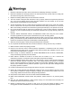
Warnings 1. Read and understand the entire owner's manual before attempting assembly or operation. 2. Read and understand the warnings posted on the machine and in this manual. Failure to comply with all of these warnings may cause serious injury. 3. Replace the warning labels if they become obscured or removed. 4. This drum sander is designed and intended for use by properly trained and experienced personnel only.
22. USE THE RIGHT TOOL at the correct speed and feed rate. DO NOT FORCE A TOOL or attachment to do a job for which it was not designed. The right tool will do the job better and safer. 23. USE RECOMMENDED ACCESSORIES; improper accessories may be hazardous. 24. MAINTAIN TOOLS IN TOP CONDITION. Keep tools sharp and clean for safe and best performance. Dull tools increase noise levels and can cause kickbacks and glazed surfaces. Check the condition and adjustment of the tools before making any cuts. 25.
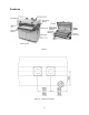
Features Figure 1 Figure 2 – Dust Port Locations 6
Specifications Model Number .................................................... DDS-225 ....................... DDS-237 ....................... DDS-237 Stock Number ..................................................... 1791290 ........................ 1791320 ........................ 1791321 Main Motor .......................................................see below ...................... see below ...................... see below Main Motor Speed (RPM) ........................................ 1,725 ......
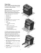
Unpacking Open the shipping crate and check for shipping damage. Report any damage immediately. Read the owner’s manual thoroughly for assembly, maintenance and safety instructions. Shipping Contents Note 1: Some parts are inside a box in the cabinet. Note 2: Models DDS-225 and DDS-237 Drum Sanders come from the factory with the first set of abrasive strips installed with 80 grit sandpaper on the front drum and 100 grit on the rear drum.
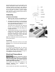
Exposed metal surfaces, such as the shafts on the drums and pressure rollers, have been given a protective coating at the factory. This should be removed with a soft cloth moistened with kerosene. Do not use acetone, gasoline, or lacquer thinner for this purpose. Do not use solvents on plastic parts, and do not use an abrasive pad because it may scratch the surfaces. Assembly Handwheel Assembly 1. Slide the post up into the handwheel and secure with the set screws, as shown in Fig 6. 2.
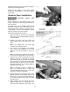
permanent wiring system; or to a system having an equipment-grounding conductor. Make sure the voltage of your power supply matches the specifications on the motor plate of the machine Abrasive Paper Installation Disconnect machine from power source. Proper attachment of the abrasive strips to the drums is important for achieving top performance from the sander.
drum. Continue to wrap the abrasive in a clockwise spiral fashion by rotating the drum with your left hand and guiding the strip with your right hand (Fig. 11). Successive windings of the strip should be flush with previous windings without any overlap. 7. The left end of the drum which contains the recess is an independent piece (Fig. 12) that can be rotated on the drum. This fastener is spring-tensioned to take up any slack and hold the abrasive strip firmly to the drum.
Pressure Rollers The pressure rollers (Fig. 15) maintain tension upon the workpiece as it passes through the machine. The spring tension of the pressure rollers has been factory set. If a board refuses to pass through the machine, or the finished surface of a board is uneven, the spring tension of the pressure rollers may need adjusting. 1. Loosen the hex nut (A, Fig. 15). 2. Place a 17mm wrench over the flat on adjusting screw (B, Fig.
4. Insert a tool, such as a hex wrench or screwdriver, through the hole on top of the leadscrew (Fig 18) at that corner of the table that is lowest. 5. Turn the leadscrew clockwise to raise the table. 6. When the adjustment is complete, install the chain over the four sprockets, and over the chain tensioner roller. Push back the chain tensioner assembly until proper tension is achieved, then tighten the socket head cap screw on the chain tensioner. 7. Install front and rear cover plates.
Conveyor Belt Conveyor belt tension and tracking adjustments may occasionally be necessary during break-in and normal operation to compensate for belt stretching. Adjust the tension of the conveyor belt by turning the knobs (Fig. 20) clockwise to increase tension, counterclockwise to decrease tension. The belt should have just enough tension to move the material without slipping on the drive roller. Do not over tighten the conveyor belt.
Pulley Alignment The drum and motor pulleys must be in line so that the belts are straight. To check this: Place a straight edge, such as a metal ruler, against the flat sides of the motor pulley and a drum pulley (Fig. 23). If the straight edge does not lie flush on the flat sides of the pulleys, loosen the set screw on the motor pulley (Fig. 22). Move the motor pulley on the shaft until the straight edge lies flush on both pulleys. Tighten the set screw.
type of wood, and feed rate. For best results, use scrap wood to practice sanding and to develop skill and familiarity with the machine before doing finish work. Maintenance Note: See also Maintenance Checklist on page 19. A good rule of thumb when sanding with grits finer than 80 is to lower the drum so it contacts the workpiece but drum can still be rotated by hand. When using grits coarser than 80 grit, you can lower the drum slightly more.
Edge Sanding When edge sanding, the sander will mimic the opposite edge of the stock which is lying on the conveyor belt. Because of this, it is important for the stock edge to have been ripped at the proper angle to the face before the sanding process. When edge sanding small stock, clamp several pieces together to prevent them from slipping on the conveyor belt. Sanding Imperfect Stock When sanding stock with a cup or crown, place the crown up.
from the drum and reversing it. To do this, remove the strip and use what was the trailing end as the starting end on the right side of the drum. Reversing the strip will provide a fresh set of cutting edges on the abrasive. Cloth backed abrasives may also be cleaned by soaking in paint thinner or mineral spirits for 20 minutes to 1 hour, then using a brush to remove any build-up or burns. Dry the abrasive strips completely before reuse. Extending Abrasive Life.
Maintenance Checklist Lubricate chain and check tension. Check belt condition - replace as needed. Dress with paraffin. Check belt tension. Check motor for loose wiring and sawdust congestion. Pulleys tight and in line. Check bearings. Replace any bad or suspect bearings immediately. Note: See also the Maintenance section on page 16. Work area around machine marked off clearly. Non-skid floor strips in area where operator normally stands.
Mechanical & Electrical Problems Problem: Machine will not start, restart, or repeatedly trips circuit breaker or blows fuses Possible Cause Solution 1. No incoming power 1. Verify unit is connected to power. 2. Overload automatic reset has not reset 2. When sander overloads on the circuit breaker built into the motor starter, it takes time for the machine to cool down before restart. Allow unit to adequately cool before attempting restart.
Parts – DDS-225 Sander Drum Assembly – DDS-225 Index No. Part No. Description Size Qty 1 ............... DDS225-101A .......... Rear Drum (serial no. 1009DDS2252795 and higher) .................................... 1 2 ............... DDS225-102A .......... Abrasive Fastener-Right (serial no. 1009DDS2252795 and higher)............... 2 3 ............... DDS225-103A .......... Abrasive Fastener-Left (serial no. 1009DDS2252795 and higher) ................. 2 4 ............... DDS225-104 ............
Drum Assembly – DDS-225 Index No. Part No. Description Size Qty 55 ............. TS-1521021 ............. Socket Set Screw ................................................. M4 x 6 ......................... 4 56 ............. DDS225-156 ............ Roll Pin ................................................................. 2 x 8mm ................... 2 57 ............. .................................
Conveyor Assembly – DDS-225 Index No. Part No. Description Size Qty 1 ............... DDS225-201 ............ Table .................................................................... .................................... 1 2 ............... DDS225-202 ............ Support Bracket, Left-Front.................................. .................................... 1 3 ............... DDS225-203 ............ Support Bracket, Right-Front ............................... ....................................
Conveyor Assembly – DDS-225 Index No. Part No. Description Size Qty 56 ............. TS-081C022............. Screw ................................................................... #10-24 x 3/8 ................ 8 57 ............. DDS237-260 ............ Boot ...................................................................... .................................... 4 59 ............. TS-0208021 ............. Socket Head Cap Screw ...................................... 5/16-18 x 1/2 ...............
Motor & Cabinet Assembly – DDS-225 Index No. Part No. Description Size Qty 1 ............... DDS225-301 ............ Cabinet ................................................................. .................................... 1 2 ............... DDS225-302 ............ Support Bracket-Front.......................................... .................................... 1 3 ............... DDS225-303 ............ Support Bracket-Rear .......................................... ...........................
Motor & Cabinet Assembly – DDS-225 Index No. Part No. Description Size Qty 48 ............. TS-081F032 ............. Phillips Pan Head Machine Screw ....................... 1/4-20 x 1/2 ................. 4 50 ............. DDS225-350 ............ Label (Drum Setting Gauge) ................................ .................................... 2 51 ............. TS-1550061 ............. Flat Washer .......................................................... M8 ............................... 1 52 .........
Motor & Cabinet Assembly – DDS-225 27
Gearbox Assembly – DDS-225 Index No. Part No. Description Size Qty 1 ............... DDS225-401A ......... Gearbox Body (serial no. 0506DDS225584 and higher) ................................ 1 2 ............... TS-0720071 ............. Lock Washer ........................................................ 1/4 ............................... 4 3 ............... TS-0207071 ............. Socket Head Cap Screw ...................................... 1/4-20 x 1-1/4.............. 4 4 ............... DDS225-404 .
Gearbox Assembly – DDS-225 Drum 29
Parts – DDS-237 Sander Drum Assembly – DDS-237 Index No. Part No. Description Size Qty 1 ............... DDS237-101B .......... Rear Drum (serial no. 1008DDS2370150 and higher ) ................................... 1 2 ............... DDS225-102A .......... Abrasive Fastener-Right (serial no. 1008DDS2370150 and higher) .............. 2 3 ............... DDS225-103A .......... Abrasive Fastener-Left (serial no. 1008DDS2370150 and higher) ................. 2 4 ............... DDS225-104 ............
Drum Assembly – DDS-237 Index No. Part No. Description Size Qty 54 ............. DDS237-154B .......... Front Drum (serial no. 1008DDS2370150 and higher ) ................................... 1 55 ............. TS-1521041 ............. Socket Set Screw ................................................. M4 x 10 ....................... 4 56 ............. DDS225-156 ............ Roll Pin ................................................................. 2 x 8mm ................... 2 57 .............
Conveyor Assembly – DDS-237 Index No. Part No. Description Size Qty 1 ............... DDS237-201 ............ Table .................................................................... .................................... 1 2 ............... DDS225-202 ............ Support Bracket, Left-Front.................................. .................................... 1 3 ............... DDS225-203 ............ Support Bracket, Right-Front ............................... ....................................
Conveyor Assembly – DDS-237 Index No. Part No. Description Size Qty 59 ............. DDS237-259 ............ Upper Bracket ...................................................... .................................... 4 60 ............. DDS237-260 ............ Boot ...................................................................... .................................... 4 61 ............. TS-081C022............. Screw ................................................................... #10-24 x 3/8 .......
Motor and Cabinet Assembly – DDS-237 Index No. Part No. Description Size Qty 1 ............... DDS237-301 ............ Cabinet ................................................................. .................................... 1 2 ............... DDS237-302 ............ Support Bracket-Front.......................................... .................................... 1 3 ............... DDS237-303 ............ Support Bracket-Rear .......................................... .........................
Motor and Cabinet Assembly – DDS-237 Index No. Part No. Description Size Qty 32 ............. TS-0207021 ............. Socket Head Cap Screw ...................................... 1/4-20 x 1/2 ................. 1 33 ............. TS-0720071 ............. Lock Washer ........................................................ 1/4 ............................. 26 34 ............. DDS237-334 ............ Shoulder Screw .................................................... M8 X1.25P X11........... 2 35 ........
Motor and Cabinet Assembly – DDS-237 Index No. Part No. Description Size Qty 85 ............. DDS237-385 ............ Powermatic Logo ................................................ .................................... 1 86 ............. DDS237-386 ............ I.D. Label (not shown) .......................................... .................................... 1 87 ............. TS-2361101 ............. Lock Washer ........................................................ M10 .........................
Gearbox Assembly – DDS-237 Index No. Part No. Description Size Qty 1 ............... DDS225-401A .......... Gearbox Body ...................................................... .................................... 1 2 ............... TS-0720071 ............. Lock Washer ........................................................ 1/4 ............................... 4 3 ............... TS-0207071 ............. Socket Head Cap Screw ...................................... 1/4-20 x 1-1/4.............. 4 4 ......
Gearbox Assembly – DDS-237 38
Optional Accessories The optional accessories listed below are available for use with DDS-225 and DDS-237 Drum Sanders. Ready-To-Cut Abrasive Strips Part No. Description Normal Use 60-9036 ...... 36 Grit Sandpaper...........surfacing rough-sawn boards, stock and glue removal 60-9060 ....... 60 Grit Sandpaper...........surfacing and dimensioning boards, truing warped boards 60-9080 ....... 80 Grit Sandpaper...........surfacing, light dimensioning, removing planer ripples 60-9100 .......
Wiring Diagrams DDS-225 Sander LIMITED SWITCH BLACK GREEN BLACK WHITE 250VAC 150MFD A1 5L3 13NO 250VAC 200MFD 18 GROUND 17 4T2 6T3 14NO 2T1 4T2 6T3 450VAC 30UF GREEN GREEN 97 98 GREEN 95 96 BLACK BLACK RED RED A2 2T1 RED GREEN REVERSING SWITCH RED FRONT BACK R U 5 S 6 V 4 5 RED RED BLACK WHITE WHITE 6 BLACK YELLOW YELLOW GREEN GREEN BLACK GREEN BLACK RED 1L2 3L2 BLACK RED BLACK WHITE 1 350VAC 10UF 40
DDS-237 Sander – 7.
DDS-237 Sander – 10HP, 3Ph, 230V LIMITED SWITCH BLACK GREEN WHITE 5L3 13NO 4T2 6T3 14NO 18 GROUND 17 1L2 3L2 GREEN A2 V1 W1 U2 V2 W2 Z1 X1 Y1 W U V REVERSING SWITCH BLACK WHITE RED BACK FRONT U L2 L1 V BLACK RED BLACK RED WHITE WHITE GREEN GREEN W L3 U1 V1 W1 U5 V5 W5 U2 V2 W2 42 WHITE 98 RED 96 GREEN 97 GREEN 95 GREEN BLACK RED BLACK 6T3 WHITE 4T2 RED WHITE 2T1 U1 BLACK 2T1 GREEN RED BLACK WHITE A1 RED WHITE WHITE BLACK BLACK
DDS-237 Sander – 10HP, 3Ph, 460V LIMITED SWITCH BLACK GREEN WHITE 5L3 13NO 4T2 6T3 14NO 18 GROUND 17 1L2 3L2 GREEN A2 X1 Y1 W2 U2 V2 U1 V1 W1 W U V REVERSING SWITCH BLACK WHITE RED BACK FRONT U L2 L1 V U1 V1 BLACK RED BLACK RED WHITE WHITE GREEN GREEN W L3 W1 U5 V5 W5 U2 V2 W2 43 WHITE 98 RED 96 GREEN 97 GREEN 95 GREEN BLACK RED BLACK 6T3 WHITE 4T2 RED WHITE 2T1 Z1 BLACK 2T1 GREEN RED BLACK WHITE A1 RED WHITE WHITE BLACK BLACK
427 New Sanford Road LaVergne, Tennessee 37086 Phone: 800-274-6848 www.powermatic.