
Use and Care Manual

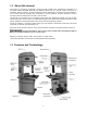
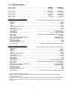

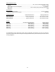
Table Of Contents
- 18-, 20-, 24-inch Band Saws
- 1.0 Warranty and service
- 2.0 Table of contents
- 3.0 IMPORTANT SAFETY INSTRUCTIONS
- 4.0 About this manual
- 5.0 Features and Terminology
- 6.0 Specifications
- 7.0 Base hole centers
- 8.0 Setup and assembly
- 8.1 Shipping contents
- 8.2 Unpacking
- 8.3 Spotting the band saw
- 8.4 Rear rail
- 8.5 Front rail and guide rail
- 8.6 Fence assembly
- 8.7 Resaw fence
- 8.8 Fence to table clearance
- 8.9 Setting cursor (zero) position
- 8.10 Setting table parallel to blade
- 8.11 Setting fence parallel to blade
- 8.12 Fence locking tightness
- 8.13 Dust collection
- 9.0 Electrical connections
- 10.0 Adjustments
- 11.0 Operating controls
- 12.0 Operation
- 13.0 Maintenance
- 14.0 Blade Selection
- 15.0 Blade Selection Guide
- 16.0 Troubleshooting PM1800B/2013B/2415B Band Saws
- 17.0 Replacement Parts
- 17.1.1 Complete Machine with Accessories – PM 1800B & 2013B Exploded View I
- 17.1.2 Complete Machine with Accessories – PM 1800B & 2013B Exploded View II
- 17.1.3 Complete Machine with Accessories – PM2415B Exploded View I
- 17.1.4 Complete Machine with Accessories – PM2415B Exploded View II
- 17.1.5 Complete Machine with Accessories – PM1800B, PM2013B and PM2415B – Parts List
- 17.2.1 Upper Wheel Assembly – Exploded View
- 17.2.2 Upper Wheel Assembly – Parts List
- 17.3.1 Lower Wheel Assembly – Exploded View
- 17.3.2 Lower Wheel Assembly – Parts List
- 17.4.1 Upper Wheel Sliding Bracket Assembly –Exploded View
- 17.4.2 Upper Wheel Sliding Bracket Assembly –Part List
- 17.5.1 Brake Linkage Assembly – Exploded View
- 17.5.2 Brake Linkage Assembly – Parts List
- 17.6.1 Lower Blade Guide Support Assembly – Exploded View
- 17.6.2 Lower Blade Guide Support Assembly – Parts List
- 17.7.1 Upper Blade Guide Support Assembly – Exploded View
- 17.7.2 Upper Blade Guide Support Assembly – Parts List
- 17.8.1 Trunnion Support Bracket Assembly – Exploded View
- 17.8.2 Trunnion Support Bracket Assembly – Parts List
- 17.9.1 Guide Bar Bracket Assembly – Exploded View
- 17.9.2 Guide Bar Bracket Assembly – Parts List
- 17.10.1 Gear Bracket Assembly – Exploded View
- 17.10.2 Gear Bracket Assembly – Parts List
- 17.11.1 Miter Gauge Assembly – Exploded View
- 17.11.2 Miter Gauge Assembly – Parts List
- 17.12.1 Fence Assembly – Exploded View
- 17.12.2 Fence Assembly – Parts List
- 18.0 Electrical Connections

7
4.0 About this manual
This manual is provided by Powermatic covering the safe operation and maintenance procedures for a
Powermatic Model PM1800B, PM2013B and PM2415B Band Saw. This manual contains instructions on
installation, safety precautions, general operating procedures, maintenance instructions and parts breakdown.
Your machine has been designed and constructed to provide consistent, long-term operation if used in
accordance with the instructions as set forth in this document.
This manual is not intended to be an exhaustive guide to band saw operational methods, use of jigs or after-
market accessories, choice of stock, etc. Additional knowledge can be obtained from experienced users or trade
articles. Whatever accepted methods are used, always make personal safety a priority.
If there are questions or comments, please contact your local supplier or Powermatic. Powermatic can also be
reached at our web site: www.powermatic.com.
Retain this manual for future reference. If the machine transfers ownership, the manual should accompany it.
Read and understand the entire contents of this manual before attempting assembly or
operation! Failure to comply may cause serious injury!
Register your product using the mail-in card provided, or register online:
http://www.powermatic.com/us/en/service-and-support/product-registration/
5.0 Features and Terminology
Figure 1