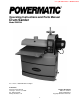
This .pdf document is bookmarked Operating Instructions and Parts Manual Drum Sander Model PM2244 For serial no. 180622441282 and higher Powermatic 427 New Sanford Road LaVergne, Tennessee 37086 Ph.: 800-274-6848 www.powermatic.com Part No.
other reproductive harm. (California Health and Safety Code Section 25249.6) 12. Do not operate this machine while tired or under the influence of drugs, alcohol or any medication. 1.0 IMPORTANT SAFETY INSTRUCTIONS WARNING – To reduce risk of injury: 13. Make certain the switch is in the OFF position before connecting the machine to the power supply. 1. 14. Make certain the machine is properly grounded. 2. Read and understand the entire owner's manual before attempting assembly or operation.
27. Maintain tools with care. Keep conveyor and abrasives clean for the best and safest performance. Follow instructions for lubricating and changing accessories. 33. Always feed stock against the rotation of drum. 34. Keep hands clear when feeding parts onto the conveyor. The part will be forced down as it begins to feed, causing a pinching action between the part and the conveyor bed. Never reach into a running machine.
3.0 Table of contents Section Page 1.0 IMPORTANT SAFETY INSTRUCTIONS ....................................................................................................... 2 2.0 About this manual .......................................................................................................................................... 3 3.0 Table of contents ............................................................................................................................................ 4 4.
4.0 Specifications Model number .....................................................................................................................................................PM2244 Stock number ..................................................................................................................................................... 1792244 Motor and electricals: Drum motor: Motor type ................................................................................
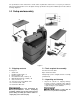
The specifications in this manual were current at time of publication, but because of our policy of continuous improvement, Powermatic reserves the right to change specifications at any time and without prior notice, without incurring obligations. 5.0 Setup and assembly Figure 2 5.1 Shipping contents 5.2 Tools required for assembly See Figure 2.
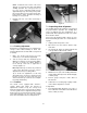
2. 5.7 Dust Collection Remove any screws or blocks holding sander to pallet. Carefully slide sander off pallet (NOTE: There are internal blocks on the pallet securing the sander – lift up on sander end to clear these while sliding off pallet.) Dust collection is mandatory for a safe work environment and extended abrasive life. The PM2244 is equipped with a 4-inch dust collection port.
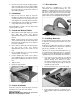
4. Continue to wrap abrasive in spiral fashion by rotating drum with one hand and guiding strip with the other. See Figure 6. 6.0 Electrical connections All electrical connections must be done by a qualified electrician in compliance with all local codes and ordinances. Failure to comply may result in serious injury. Successive windings of strip must not have any overlap. They should be flush with previous windings or with a slight gap between. The last winding should have a 1/16 to 1/8 in.
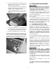
This tool is intended for use on a circuit that has an outlet that looks like the one illustrated in A, Figure 8. An adapter, shown in B and C, may be used to connect this plug to a 2-pole receptacle as shown in B if a properly grounded outlet is not available. The temporary adapter should be used only until a properly grounded outlet can be installed by a qualified electrician. This adapter is not permitted in Canada.
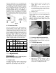
NOTE: Insufficient belt tension will cause slippage of conveyor belt on drive roller during sanding operation. The conveyor belt is too loose if it can be stopped by hand pressure applied directly to top of moving conveyor belt. Excessive belt tension can result in bent rollers, bent brackets, and/or premature wearing of bushings or conveyor belt. 3. Reinstall left side cover when tensioning is complete. Figure 12 7.
7.4.1 Verifying drum alignment Note: This is an operational test. Perform this procedure only after you have become familiar with sander operation. When sanding boards wider than the drum, table alignment is critical and table must be adjusted exactly level to slightly lower on the outboard end. This will prevent any ridges from developing in the stock. Always check this on a piece of scrap wood, as follows, before sanding the work piece. 1.
8.3 Drum motor operation 8.0 Operations Before using your drum sander, review the previous sections on initial set-up and adjustment. Before operating, make sure an abrasive strip is mounted and a proper dust collection system is connected. 1. Connect power supply to machine. – Display remains dark. 2. Turn on main power switch (A). – Display will illuminate. Racetrack (G) may flash continuously, indicating that emergency stop is still engaged. 3.
When handwheel is rotated to move drum downward below zero point, a negative sign will appear before the depth number (K). 2. 3. 4. Width of piece being processed. Hardness of piece. Feed rate of conveyor belt. NOTE: Drum height will remain in control panel memory if E-stop button is pressed. Drum height will not remain in memory if main power switch is turned OFF. 8.
If there is a significant thickness difference, the thinner pieces can slip on the conveyor belt if they do not contact the tension rollers. Also note that pieces thicker than 3/4” should be longer than the minimum normally recommended to prevent tipping of the stock. If the finish is still affected, make adjustments by slowing the conveyor and/or decreasing the depth of cut and run the stock through again.
9.2 Drum maintenance on the motor. Note that to get the best final finish, however, the stock should be fed through the machine so it will be sanded in line with the grain of the wood on the final one or two passes. The drum should not require removal from the machine under normal circumstances. Should maintenance ever become necessary, the drum has been designed for easy removal and replacement. 9.0 Maintenance Remove four socket head screws (C, Figure 19).
10.0 Optional abrasives Each abrasive comes in pack of 3. 1792201 1792202 1792203 1792204 1792205 1792206 1792207 1792208 PM2244 Precut Abrasive 36G (qty. 3) PM2244 Precut Abrasive 60G (qty. 3) PM2244 Precut Abrasive 80G (qty. 3) PM2244 Precut Abrasive 100G (qty. 3) PM2244 Precut Abrasive 120G (qty. 3) PM2244 Precut Abrasive 150G (qty. 3) PM2244 Precut Abrasive 180G (qty. 3) PM2244 Precut Abrasive 220G (qty. 3) 10.
11.0 Tracker kit 7. With first tracker installed, slide conveyor belt into bottom slot of tracker. Note: When installed properly, only bottom lip of tracker will be visible. The top slot can be used if bottom slot wears out. 8. Install second tracker opposite the first. Use both trackers unless the second one does not fit in conveyor or unless conveyor belt is damaged. 9. Turn conveyor table right-side up and reposition it onto sander. Re-attach three (3) mounting screws and tighten.
accept stains evenly. This will vary by type of wood. Oak, for example, is susceptible to burnishing because of its open pores. 12.0 Abrasives The abrasive material you choose will have a substantial effect on the performance of your sander. Variations in paper type, weight, coating and durability all contribute to achieving your desired finish. 12.2 Cleaning abrasive strips Regularly clean the abrasive strip on the drum with commercially available cleaning sticks, following the manufacturer’s directions.
13.0 Troubleshooting the PM2244 Drum Sander Symptom Drum motor won’t start when ON button is pushed. Possible Cause Correction * No incoming current. Check connections at plug or circuit panel. Safety key missing from switch. Install safety key. E-stop still engaged (racetrack is flashing). Conveyor speed dial not reset after using E-stop (racetrack is flashing). Low voltage. Disengage E-stop by rotating clockwise. Open circuit in motor or loose connection.
14.1.
14.1.
14.1.
14.1.4 PM2244 Head Assembly – Parts List Note: Some parts may be listed for reference only and not available individually. Index No Part No Description Size Qty 1 ................ PM2244-101.............. Dust Hood ................................................................ ...................................... 1 2 ................ JCH4-16 .................... Spring Pin ................................................................ 3*35 .............................. 2 3 ................
Index No Part No Description Size Qty 56 .............. PM2244-156.............. Scale ....................................................................... ...................................... 1 57 .............. F002631 .................... Flat Washer ............................................................. 4.3*10*1.0T ................... 6 58 .............. PM2244-158.............. Self Tapping Screw.................................................. M4*1.59P*25L ............... 4 59 .......
Index No Part No Description Size Qty 113 ............ F008750 .................... Hex Cap Screw ........................................................ M6*1.0P*25L ................. 1 114 ............ BB-51101 .................. Thrust Bearing ......................................................... 51101 ............................ 1 115 ............ PM2244-1115............ Table Micro-Adjusting Knob .................................... ...................................... 1 116 ............
14.2.
14.2.2 PM2244 Conveyor Bed Assembly – Parts List Index No Part No Description Size Qty 1 ................ PM2244-201.............. Conveyor Belt .......................................................... ...................................... 1 2 ................ PM2244-202.............. Driven Roller Holder ................................................ ...................................... 2 3 ................ PM2244-203.............. Oilite Bushing..................................................
14.3.1 PM2244 Cabinet Assembly – Exploded View 14.3.2 PM2244 Cabinet Assembly – Parts List Index No Part No Description Size Qty 1 ................ PM2244-301.............. Cabinet Door............................................................ ...................................... 1 2 ................ PM2244-302.............. Door Latch ............................................................... ...................................... 1 3 ................ PM2244-303.............. Foam Strip .....
15.
16.0 Warranty and service Powermatic warrants every product it sells against manufacturers’ defects. If one of our tools needs service or repair, please contact Technical Service by calling 1-800-274-6846, 8AM to 5PM CST, Monday through Friday. Warranty Period The general warranty lasts for the time period specified in the literature included with your product or on the official Powermatic branded website. • Powermatic products carry a limited warranty which varies in duration based upon the product.
This page intentionally left blank.
427 New Sanford Road LaVergne, Tennessee 37086 Phone: 800-274-6848 www.powermatic.
Manuel d’utilisation et liste des pièces Ponceuse à tambour Modèle PM2244 Pour le numéro de série 180622441282 et plus Powermatic 427 New Sanford Road La Vergne, Tennessee 37086, États-Unis Tél.: +1-800-274-6848 www.powermatic.com Réf.
12. Ne pas utiliser cette machine en cas de fatigue ou sous l’emprise de drogues, d’alcool ou de médicaments. 13. S’assurer que l’interrupteur est en position OFF (arrêt) avant de brancher la machine à la source d’alimentation. 14. S’assurer que la machine est correctement mise à la terre. 1.0 CONSIGNES IMPORTANTES DE SÉCURITÉ 15. Débrancher la machine de la source d’alimentation avant de réaliser tous les réglages ou toute la maintenance. 16. Retirer les clés de réglage.
des pièces sur le convoyeur. La pièce sera attirée vers le bas lorsqu’elle commencera à rentrer dans la machine, entraînant un pincement entre la pièce et le tapis du convoyeur. Ne jamais tenter d’introduire les mains dans une machine qui fonctionne. Mettre la ponceuse hors tension, la laisser s’arrêter complètement, et débrancher l’alimentation, avant d’essayer de récupérer des pièces par la partie qui se trouve en-dessous du tambour. 28. Mettre la machine hors tension avant de la nettoyer.
3.0 Table des matières Section Page 1.0 CONSIGNES IMPORTANTES DE SÉCURITÉ ......................................................................................................................... 2 2.0 À propos du présent manuel ...................................................................................................................................................... 3 3.0 Table des matières .........................................................................................................
4.0 Spécifications Numéro de modèle................................................................................................................................................................... PM2244 Numéro de référence du matériel................................................................................................................... ........................ 1792244 Moteur et composants électriques : Moteur du tambour : Type de moteur............................. ..........................
Les spécifications fournies dans le présent manuel étaient valables au moment de la publication, mais du fait de sa politique d’amélioration perpétuelle, Powermatic se réserve le droit de modifier ces spécifications à tout moment sans en avertir au préalable l’utilisateur, et sans aucune autre obligation. 5.0 Préparation et montage Figure 2 5.1 Contenu du conditionnement expédié 5.2 Outils nécessaires pour le montage Voir Figure 2.
2. 5.7 Aspiration de la poussière Retirer toutes vis ou blocs fixant la ponceuse à lapalette. Faire glisser doucement la ponceuse hors de la palette (NOTA : La palette contient des blocs internes qui fixent la ponceuse : Soulever légèrement la ponceuse par un des côtés afin d’enlever ces blocs tout en la faisant glisser hors de la palette.) L’aspiration de la poussière est obligatoire pour que l’environnement de travail soit sûre et que les matériaux abrasifs durent longtemps.
4. Continuer à enrouler l’abrasif en spirale en faisant tourner le tambour d’une main tout en guidant la bande de l’autre. Voir Figure 6. 6.0 Branchements électriques Tous les branchements électriques doivent être effectués par un électricien agréé selon l’ensemble des codes et règlements locaux. En cas de nonrespect de cette consigne, vous vous exposez à un risque de graves blessures. Il ne doit pas y avoir plusieurs couches de bandes superposées lors de l’enroulement.
Cette machine est conçue pour être utilisée sur un circuit équipé d’une prise qui ressemble à celle illustrée dans la partie A de la Figure 8. Il est possible d’utiliser un adaptateur comme celui illustré dans les parties B et C pour brancher ce connecteur male à une prise 2 pôles, comme illustré dans la partie B en cas d’absence de prise dûment mise à la terre. L’adaptateur provisoire ne doit être utilisé que jusqu’à ce qu’une prise dûment mise à la terre soit installée par un électricien qualifié.
NOTA : Toute tension insuffisante de la courroie entraînera un glissement de la courroie du convoyeur sur le rouleau d’entraînement lors de l’opération de ponçage. S’il est possible d’arrêter la courroie du convoyeur alors qu’elle est en fonctionnement en mettant simplement la main dessus, alors elle est trop lâche. Une tension excessive de la courroie peut entraîner une torsion des rouleaux, des supports, et une usure prématurée des bagues ou de la courroie du convoyeur. 3.
7.4.1 Vérification de l’alignement du tambour Nota : Il s’agit d’un test opérationnel. N’effectuez cette procédure que si vous avez l’habitude d’utilisez une ponceuse. Lorsque les plateaux de ponçage sont plus larges que le tambour, cela signifie que l’alignement de la table est critique et que la table doit être réglée au niveau exact de sorte qu’elle soit légèrement en-dessous côté extérieur. Cela permettra d’éviter toute formation de stries au niveau du bois.
8.0 Utilisation 8.3 Avant d’utiliser votre ponceuse à tambour, consultez les sections qui traitent de la configuration et du réglage initial. Avant d’utiliser la machine, assurez-vous qu’une bande abrasive a été installée et qu’elle est reliée à un système adéquat d’aspiration de la poussière. 8.1 1. 2. Procédure d’utilisation de base 3. Régler la profondeur de coupe. Mettre en route le système d’aspiration de la poussière. Mettre en route le tambour de ponçage.
Si vous tournez le volant pour abaisser le tambour en dessous du niveau zéro, un signe négatif apparaîtra avant le chiffre (K) indiquant la profondeur. 2. 3. 4. NOTA : La hauteur du tambour sera conservée dans la mémoire du tableau de commande si vous appuyez sur le bouton d’arrêt d’urgence. La hauteur du tambour ne sera pas conservée dans la mémoire si vous mettez l’interrupteur principal sur OFF (arrêt). La largeur de la pièce à poncer. La dureté de la pièce. La vitesse d’avance de la courroie. 8.
Si la finition est toujours affectée, procéder à des réglages en réduisant la vitesse du convoyeur et la profondeur de coupe et insérer à nouveau la pièce de bois. En cas de différence d’épaisseur trop importante, les pièces les plus fines risquent de glisser sur la courroie du convoyeur si elles ne sont pas en contact avec les rouleaux tendeurs.
9.2 imposées au moteur. Notez toutefois que pour obtenir la finition parfaite, la pièce de bois doit être insérée dans la machine de sorte à ce qu’elle soit poncée en fonction du grain du bois lors du ou des deux derniers passages. 9.0 Il n’est pas nécessaire de retirer le tambour de la machine dans des circonstances normales. S’il devient nécessaire de procéder à la maintenance, le tambour a été conçu de sorte à être déposer et remplacer facilement.
10.0 Matériaux abrasifs en option Chaque abrasive est fourni par lot de 3.
11.0 Kit de centrage 7. Après avoir au préalable installé le premier dispositif de centrage, faites glisser la courroie dans la fente inférieure du dispositif de centrage. Nota : S’il est bien installé, seule la languette inférieure est visible. Il est possible d’utiliser la fente supérieure en cas d’usure de la fente inférieure. 8. Installez le second dispositif de centrage à l’opposé du premier.
12.0 Abrasifs certaines teintures adhéreront difficilement et de façon nonuniforme. Cela dépendra du type de bois. Le chêne, par exemple, est susceptible de brûler à cause de ses pores ouverts. Le matériau abrasif sélectionné aura un impact sur les performances de votre ponceuse. Utiliser différents types de papier, de poids, de revêtement et de durabilité différente vous aidera à atteindre la finition souhaitée. 12.1 12.
13.0 Dépannage de la ponceuse à tambour PM2244 Symptômes Le moteur du tambour ne démarre pas lorsque vous appuyez sur le bouton ON. Le moteur ne se met pas en route :les fusibles explosent ou les disjoncteurs sautent. Cause possible Absence de courant entrant. La clé de sécurité n’est pas sur l’interrupteur. Vérifiez les branchements au niveau de la prise ou du tableau du circuit. Mettre la clé de sécurité. L’arrêt d’urgence est toujours engagé (le voyant « racetrack » clignote).
14.1.
14.1.
14.1.
14.1.4 Ensemble tête de la ponceuse PM2244 –Liste des pièces Nota : Il se peut que certaines pièces soient mentionnées uniquement à titre de référence et qu’elles ne soient pas disponibles individuellement. N° de repère Réf Désignation Taille Qté 1 ......................PM2244-101........................Hotte à poussière ................................................................................................................................. 1 2 .....................JCH4-16 ....................
N° de repère Réf Désignation Taille Qté 56 ...................PM2244-156.............. Échelle ............................................................................................................................................................1 57 ..................F002631 .................... Rondelle plate ............................................................................................. 4,3 x 10 x 1,0T............................6 58 .................. PM2244-158..............
N° de repère Réf Désignation Taille Qté 113 ................F008750 .................... Vis d’assemblage à tête hexagonale........................................................... M6 x 1,0P x 25L ........................1 114 ................BB-51101 .................. Roulement de butée ...................................................................................... 51101........................................1 115 ................PM2244-1115............ Bouton de micro-réglage de la table ..
14.2.
14.2.2 Ensemble tapis du convoyeur de la ponceuse PM2244 –Liste des pièces N° de repère Réf Désignation Taille Qté 1 .....................PM2244-201.............. Courroie du convoyeur .................................................................................................................................... 1 2 ..................... PM2244-202.............. Support du rouleau entraîné ...............................................................................................................
14.3.1 Ensemble armoire de la ponceuse PM2244 – Vue éclatée 14.3.2 Ensemble armoire de la ponceuse PM2244 –Liste des pièces N° de repère Réf Désignation Taille Qté 1 .................... .PM2244-301.............. Porte d’armoire ................................................................................................................................................1 2 ....................PM2244-302.............. Loquet de porte......................................................................
15.
16.1 Garantie et entretien Powermatic garantit chaque produit vendu contre les défauts de fabrication. Si l’un de nos produits nécessite un entretien ou une réparation, merci de contacter le Service Technique en appelant au numéro suivant : +1-800-274-6846, de 8h00 à 17h00 CST (heure normale du centre), du lundi au vendredi. Période de garantie La garantie générale court sur la période spécifiée dans les documents que vous avez reçu avec votre produit ou sur le site officiel de Powermatic.
La présente page a intentionnellement été laissée vierge.
427 New Sanford Road La Vergne, Tennessee 37086, États-Unis Téléphone : +1 800-274-6848 www.powermatic.
Manual de instrucciones de operación y piezas Lijadora de tambor Modelo PM2244 Para el número de serie 180622441282 and y superior Powermatic 427 New Sanford Road LaVergne, Tennessee 37086 Tel: 800-274-6848 www.powermatic.com No.
por el Estado de California como causante de cáncer. Evitar la inhalación de polvo que se genera a partir de productos de madera o utilizar una mascarilla contra el polvo u otras medidas de seguridad para evitar la inhalación de polvo que se genera a partir de productos de madera. 1.0 INSTRUCIONES DE SEGURIDAD IMPORTANTES 11. Productos de madera emiten sustancias químicas conocidas en el Estado de California como causa defectos de nacimiento u otros daños reproductivos.
23. Preste toda la atención a su trabajo. Mirar alrededor, mantener una conversación y “jugar” son acciones descuidadas que pueden provocar lesiones graves. 30. No deje nunca la máquina funcionando de forma desatendida. Desconecte la corriente y no deje que la máquina se pare completamente. 31. Quite los artículos sueltos y las piezas de trabajo innecesarias del área antes de arrancar la máquina. 24. Mantenga una posición equilibrada en todo momento de modo que no pueda caer en piezas móviles.
¡Lea y entienda todo el contenido de este manual antes de tratar de armar o hacer funcionar! ¡De no cumplir con esto se pueden producir lesiones graves! 3.0 Índice Sección Página 1.0 INSTRUCIONES DE SEGURIDAD IMPORTANTES ..................................................................................... 2 2.0 Acerca de este manual .................................................................................................................................. 3 3.0 Índice...............................
14.2.1 Conjunto de cabeza de lecho de banda transportadora de PM2244 – Vista desarrollada ................. 29 14.2.2 Conjunto de cabeza de lecho de banda transportadora de PM2244 – Lista de piezas ...................... 30 14.3.1 Conjunto de gabinete de PM2244 – Vista desarrollada ...................................................................... 31 14.3.2 Conjunto de gabinete de PM2244 – Lista de piezas ........................................................................... 31 15.
4.0 Especificaciones Número de modelo ................................................................................................................................ PM2244 Número de artículo ............................................................................................................................... 1792244 Motor y dispositivos eléctricos: Motor de la lijadora Tipo de motor ..........................
Las especificaciones en este manual eran las reales en el momento de la publicación, pero debido a nuestra política de mejora continua, Powermatic se reserva el derecho de cambiar las especificaciones en cualquier momento sin previo aviso, sin incurrir en obligaciones. 5.0 Configuración y armado Figura 2 5.1 Contenido de envío armado. De no cumplir con esto se pueden producir lesiones graves. Vea la Figura 2. 1 1 2 2 2 2 16 16 16 5.
2. 5.6 Perillas de traba de las ruedas orientables Quite los tornillos o bloques que sujetan la lijadora a la paleta. Deslice cuidadosamente la lijadora fuera de la paleta (NOTA: Hay bloques internos en la paleta que sujeta la lijadora – levante el extremo de la lijadora para no hacer contacto con ellos mientras se desliza y se saca de la paleta). Enrosque las perillas de traba de las ruedecillas orientables (E, Figura 2) en los agujeros roscados del lado del gabinete.
2. Suelte la palanca del sujetador para fijar el extremo de la tira. Figura 7 Figura 5 3. 4. Empiece a envolver el abrasivo alrededor del tambor. El borde ahusado del extremo de la tira debe seguir el borde del tambor. Siga enrollando el abrasivo en forma espiral girando el tambor con una mano y guiando la tira con la otra. Vea la Figura 6. Los arrollamientos sucesivos de la tira no deben solaparse. Deben estar al ras con los arrollamientos previos o con una ligera separación entre ellos.
un recalentamiento. La Tabla 1 muestra el tamaño correcto dependiendo de la longitud del cordón y de los amperios nominales de la placa de identificación. En caso de duda, use el siguiente calibre más grueso. Cuanto más pequeño sea el número de calibre, más grueso será el cordón. descarga eléctrica. El conductor con aislamiento que tenga una superficie exterior verde con o sin franjas amarillas es el conductor de tierra del equipo.
Figura 11 Figura 9 7.2.2 Ajuste de la alineación 7.2 Tensión/alineación de la banda transportadora Tal vez sea necesario ajustar la tensión de la banda transportadora durante el período de rodaje para compensar el estiramiento de la banda. Una banda se alinea correctamente cuando se mueve centralmente sobre los rodillos de la banda transportadora sin desviarse hacia un lado. Los ajustes de alineación se efectúan mientras la banda transportadora se desplaza. 7.2.1 Ajuste de la tensión 1.
7.4 Verificación de la alineación del tambor Nota: Esta es una prueba de operación. Efectúe este procedimiento solamente después de que se haya familiarizado con la operación de la lijadora. Al lijar tableros más anchos que el tambor, la alineación de la mesa es crítica y la tabla debe ajustarse exactamente a nivel para bajar ligeramente el extremo exterior. Esto impedirá que se formen lomas en el material.
4. Arranque la banda transportadora y seleccione la velocidad de alimentación. 5. Alimente material por la máquina. Para alimentar material por la lijadora, apoye y sujete el tablero que se vaya a lijar en la banda transportadora, permitiendo que la banda transportadora transporte el tablero al tambor. Una vez que se haya alimentado la mitad del material, cámbiese de posición al lado de salida de la máquina para recibir y controlar el tablero a medida que sale. 8.
3. Gire la parada de emergencia (D) hacia la derecha para desconectar la parada. 4. Encienda el motor del tambor oprimiendo firmemente el interruptor (B) – el círculo iluminado (J) se moverá, y se iluminará “ON”. reajuste de profundidad cero (F, Figura 16) para poner a cero el ajuste de la altura del tambor desde la pieza de trabajo. El volante se usa después para bajar el tambor en incrementos exactos por cada pasada, observando la profundidad en la pantalla de control (K).
8.10 Ajuste de la profundidad de corte alimentación dependerá de un número de factores, incluido el tipo de material, el grano y la profundidad de corte usados, y si el material se alimenta directamente en línea con el lecho de la banda transportadora o en ángulo. Si se reduce la potencia del motor del tambor, si patina la banda transportadora o si observa un efecto remanente en el material, disminuya a velocidad de alimentación.
8.13 Recomendaciones para obtener el rendimiento máximo el borde del material se corte al ángulo apropiado con respecto a la cara antes del proceso de lijado. Al lijar bordes de material de menos de 3/4” de ancho o más de 2” de alto, un buen procedimiento consiste en apilar y sujetar varias piezas para impedir que patinen o se inclinen en la banda transportadora.
en el motor. Sin embargo, observe que para lograr el mejor acabado final, el material debe alimentarse por la máquina, para que se lije en línea con la veta de la madera en la pasada final o en dos pasadas en la madera. 9.0 Mantenimiento Antes de efectuar el mantenimiento de la máquina, desconéctala del suministro eléctrico tirando del enchufe o poniendo en apagado el interruptor principal. De no cumplir con esto se pueden producir lesiones graves. Figura 18 9.2 Mantenimiento del tambor 9.
Nota: Si la banda transportadora se desvía continuamente hacia un lado de la máquina, invirtiendo el sentido de desplazamiento de la banda en el lecho de la banda transportadora se puede corregir el problema. Para asegurarse de que el lecho de la banda transportadora no se tuerza, coloque un nivel sobre el lecho de la banda transportadora. Nivele la máquina si es necesario. Si sigue habiendo un problema, vaya a los pasos siguientes: esto, primero centre la banda transportadora en el lecho.
no encaje en la banda transportadora o a menos que esté dañada. 11.0 Juego de alineadores No. de material: PM2244-213 9. Los alineadores reducen considerablemente los ajustes de alineación de las bandas transportadoras. Ya están instalados en la lijadora. La información siguiente es para reajustar o reemplazar sus alineadores, si se hace necesario. 1. 2. 3. 4. Desconecte la corriente de la lijadora. Suba el tambor tan alto como pueda, y quite la cubierta lateral (vea la Figura 10).
Nota: Los granos que son demasiado finos a veces pueden bruñir la madera y dejar una superficie brillante que no aceptará los tintes por igual. Eso variará con el tipo de madera. El roble, por ejemplo, es susceptible al bruñido debido a sus poros abiertos. 12.0 Abrasivos El material abrasivo escogido tendrá un efecto sustancial en el rendimiento de su lijadora. Las variaciones en tipo, peso, revestimiento y durabilidad del papel contribuyen a lograr su acabado deseado. 12.
13.0 Resolución de problemas de la lijadora de tambor PM2244 Síntoma Causa posible El motor del tambor no No llega corriente. arranca cuando se oprime el botón de encendido. Falta la llave de interruptor. Corrección * Compruebe las conexiones en el enchufe o tablero de circuitos. seguridad del Instale la llave de seguridad. Parada de emergencia aún conectada Desconecte la parada (el óvalo está destellando). girando a la derecha.
Síntoma Causa posible Corrección * El motor de la banda No se reajustó el indicador de Gire el indicador de velocidad a la posición transportadora no velocidad de la banda transportadora de APAGADO y después trate de arrancar funciona después de usar la parada de la máquina. emergencia. El motor del tambor se para cuando se retira el dedo del interruptor de activación/desactivación del motor del tambor.
14.1.
14.1.
14.1.
14.1.4 Conjunto de cabeza de PM2244 – Lista de piezas Nota: Algunas piezas se muestran como referencia solamente y no están disponibles individualmente. No. de índice No. de pieza Descripción Tamaño Cant. 1 ................ PM2244-116.............. Tapa contra el polvo ............................................... ...................................... 1 2 ................ JCH4-16 .................... Pasador de resorte ................................................. 3*35 ..........................
No. de índice No. de pieza Descripción Tamaño Cant. 56 .............. PM2244-156.............. Escala ..................................................................... ...................................... 1 57 .............. F002631 .................... Arandela plana ....................................................... 4.3*10*1.0T ................... 6 58 .............. PM2244-158.............. Tornillo aterrajador .................................................. M4*1.59P*25L ...............
No. de índice No. de pieza Descripción Tamaño Cant. 113 ............ F008750 .................... Tornillo de cabeza hexagonal ................................. M6*1.0P*25L ................. 1 114 ............ BB-51101 .................. Cojinete de empuje ................................................. 51101 ............................ 1 115 ............ PM2244-1115............ Perilla de microajuste de la tabla ............................ ...................................... 1 116 ............
14.2.
14.2.2 Conjunto de cabeza de lecho de banda transportadora de PM2244 – Lista de piezas No. de índice No. de pieza Descripción Tamaño Cant. 1 ................ PM2244-201.............. Banda transportadora ............................................. ...................................... 1 2 ................ PM2244-202.............. Sujetador de rodillo impulsado ................................ ...................................... 2 3 ................ PM2244-203.............. Buje Oilite ............
14.3.1 Conjunto de gabinete de PM2244 – Vista desarrollada 14.3.2 Conjunto de gabinete de PM2244 – Lista de piezas No. de índice No. de pieza Descripción Tamaño Cant. 1 ................ PM2244-301.............. Puerta de gabinete ................................................. ...................................... 1 2 ................ PM2244-302.............. Pestillo de puerta .................................................... ...................................... 1 3 ................
15.
16.0 Garantía y servicio Powermatic garantiza que todos los productos que vende no tienen defectos de fabricante. Si una de nuestras herramientas necesita servicio o reparación, póngase en contacto con Servicio Técnico llamando al 1-800-274-6846, 8 de la mañana a 5 de la tarde, Hora Central, de lunes a viernes. Período de garantía La garantía general dura el tiempo especificado en las publicaciones incluidas con su producto o en el sitio web oficial de la marca Powermatic.
34
35
427 New Sanford Road LaVergne, Tennessee 37086 Teléfono: 800-274-6848 www.powermatic.