
Use and Care Manual

9
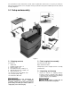
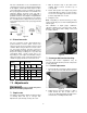
This tool is intended for use on a circuit that has an
outlet that looks like the one illustrated in A, Figure
8. An adapter, shown in B and C, may be used to
connect this plug to a 2-pole receptacle as shown in
B if a properly grounded outlet is not available. The
temporary adapter should be used only until a
properly grounded outlet can be installed by a
qualified electrician. This adapter is not permitted in
Canada. The green-colored rigid ear, lug, and the
like, extending from the adapter must be connected
to a permanent ground such as a properly grounded
outlet box.
Figure 8
6.2 Extension cords
The use of extension cords is discouraged; try to
position machines near the power source. If an
extension cord is necessary, make sure it is in good
condition. When using an extension cord, be sure to
use one heavy enough to carry the current your
product will draw. An undersized cord will cause a
drop in line voltage resulting in loss of power and
overheating. Table 1 shows correct size to use
depending on cord length and nameplate ampere
rating. If in doubt, use the next heavier gauge. The
smaller the gauge number, the heavier the cord.
Ampere
Rating
Volts
Total length of
cord in feet
More
Than
Not
More
Than
120
240
25
50
50
100
100
200
150
300
AWG
00 06 18 16 16 14
06 10 18 16 14 12
10 12 16 16 14 12
12 16 14 12
Not
Recommended
Table 1: Extension cord recommendations
7.0 Adjustments
Disconnect sander from power
source before making adjustments.
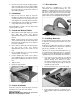
7.1 Depth scale
The depth scale indicates distance between bottom
of sanding drum and top of conveyor belt.
Adjustment is performed by “zeroing” the scale.
1. With an abrasive strip on the drum, lower
sanding drum to where it touches top of
conveyor belt.
2. At this drum position, the depth scale pointer
should align with zero mark on scale. If it does
not, loosen screw (Figure 9) and raise or lower
pointer to align with zero on scale.
3. Retighten screw.
Note: Depending on desired accuracy, you may
need to repeat this process when installing different
abrasive grits.
This calibration of depth gauge establishes
“absolute” distance from conveyor belt to drum,
while the control panel allows setting of zero point
for relative distance.
Figure 9
7.2 Conveyor belt tension/tracking
Conveyor belt tension adjustment may be
necessary during the break-in period to compensate
for belt stretching.
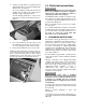
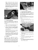
7.2.1 Tension adjustment
1. Remove left side cover (Figure 10) by removing
two socket head screws with 4mm hex wrench.
Figure 10
2. Adjust take-up screw nuts (Figure 11) with a
17mm wrench. Do this on both sides of
conveyor to obtain approximately equal tension
on both sides of sanding belt when taut.