
Use and Care Manual
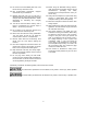
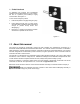

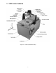

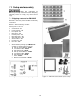
Table Of Contents
- CNC Routers
- 1.0 IMPORTANT SAFETY INSTRUCTIONS
- 1.1 Switch lock-out
- 2.0 About this manual
- 3.0 Table of contents
- 4.0 CNC router features
- 5.0 Specifications for Powermatic CNC Router Machines
- 6.0 Glossary
- 7.0 Setup and assembly
- 7.1 Shipping contents for PM-2X2R
- 7.2 Unpacking and cleanup
- 7.3 Tools required for assembly
- 7.4 Shipping contents for PM-2X4SP
- 7.5 Unpacking and cleanup
- 7.6 Tools required for assembly
- 7.7 Assembling stand (all models)
- 7.8 Installing router table on stand
- 7.9 Completing assembly
- 7.10 Installing router (PM-2X2R only)
- 7.11 Installing top guard
- 8.0 Electrical connections
- 9.0 Setup for operation
- 10.0 Operations
- 11.0 Controller functions
- 12.0 User-maintenance
- 13.0 Additional accessories
- 14.0 Troubleshooting PM-2X2R and PM-2X4SP CNC routers
- 15.0 Replacement Parts
- 15.1.1 PM-2X2R Assembly I – Exploded View
- 15.1.2 PM-2X2R Assembly II – Exploded View
- 15.1.3 PM-2X2R Assemblies – Parts List
- 15.2.1 PM-2X2S Stand Assembly – Exploded View
- 15.2.2 PM-2X2S Stand Assembly – Parts List
- 15.3.1 PM-2X4SP Assembly I – Exploded View
- 15.3.2 PM-2X4SP Assembly II – Exploded View
- 15.3.3 PM-2X4SP Assemblies – Parts List
- 15.4.1 PM-2X4S Stand Assembly – Exploded View
- 16.0 Electrical Connections for CNC Router
- 17.0 Warranty and service

10
7.0 Setup and assembly
Read and understand all
assembly and setup instructions before attempting
assembly. Failure to comply may cause serious
injury.
7.1 Shipping contents for PM-2X2R
Bold text is how each part is identified in assembly
instructions.
BOX #1 – Stand assembly, contains:
See Figures 7-1 and 7-2.
4 Cross braces – S1
2 Lower supports – S2
1 Front panel – S3
1 Rear panel – S4
1 Left side panel – S5
1 Right side panel – S6
1 Open side panel – S7
4 Swivel casters – S8
4 Leveling foot – S9
4 Hex nuts – S10
1 Stand hardware package, p/n PM2X2S-HP
consists of 3 smaller bags (Figure 20):
16 Hex cap screws M8x25 – HP001
16 Lock washers M8 – HP002
16 Flat washers M8 – HP003
16 Hex cap screws M6x12 – HP004
16 Lock washers M6 – HP005
16 Flat washers M6 – HP006
1 Hook – HP007
2 Machine screws M4x6 – HP008
Figure 7-2: stand hardware package
Figure 7-1: PM-2x2R stand contents (not to scale)