
Use and Care Manual
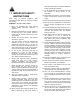
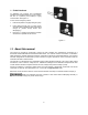


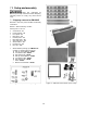
Table Of Contents
- CNC Routers
- 1.0 IMPORTANT SAFETY INSTRUCTIONS
- 1.1 Switch lock-out
- 2.0 About this manual
- 3.0 Table of contents
- 4.0 CNC router features
- 5.0 Specifications for Powermatic CNC Router Machines
- 6.0 Glossary
- 7.0 Setup and assembly
- 7.1 Shipping contents for PM-2X2R
- 7.2 Unpacking and cleanup
- 7.3 Tools required for assembly
- 7.4 Shipping contents for PM-2X4SP
- 7.5 Unpacking and cleanup
- 7.6 Tools required for assembly
- 7.7 Assembling stand (all models)
- 7.8 Installing router table on stand
- 7.9 Completing assembly
- 7.10 Installing router (PM-2X2R only)
- 7.11 Installing top guard
- 8.0 Electrical connections
- 9.0 Setup for operation
- 10.0 Operations
- 11.0 Controller functions
- 12.0 User-maintenance
- 13.0 Additional accessories
- 14.0 Troubleshooting PM-2X2R and PM-2X4SP CNC routers
- 15.0 Replacement Parts
- 15.1.1 PM-2X2R Assembly I – Exploded View
- 15.1.2 PM-2X2R Assembly II – Exploded View
- 15.1.3 PM-2X2R Assemblies – Parts List
- 15.2.1 PM-2X2S Stand Assembly – Exploded View
- 15.2.2 PM-2X2S Stand Assembly – Parts List
- 15.3.1 PM-2X4SP Assembly I – Exploded View
- 15.3.2 PM-2X4SP Assembly II – Exploded View
- 15.3.3 PM-2X4SP Assemblies – Parts List
- 15.4.1 PM-2X4S Stand Assembly – Exploded View
- 16.0 Electrical Connections for CNC Router
- 17.0 Warranty and service
9
1
subject to local/national electrical codes.
The specifications in this manual were current at time of publication, but because of our policy of continuous
improvement, Powermatic reserves the right to change specifications at any time and without prior notice, without
incurring obligations.
6.0 Glossary
CAD – Computer aided design
CAM – Computer aided manufacturing
CNC – Computer numerical control
Climb cut – Cutter rotates with direction of feed.
Climb cutting prevents tearout, but can lead to
chatter marks with a straight-fluted bit; a spiral-fluted
bit will reduce chatter.
Conventional cut – Cutter rotates against direction
of feed. Results in minimal chatter but can lead to
tearout in certain woods.
Feed rate – Speed at which the cutting tool moves
through the workpiece.
G-Code – A universal numerical control (NC)
machine tool language that specifies axis points to
which the machine will move.
Grid – The minimum movement, or feed, of the
router head. Head automatically moves to next grid
position when button is toggled in continuous or step
mode.
Home position (or machine zero) – Machine-
designated zero point determined by physical limit
switches. (It does not identify actual work origin
when processing a workpiece.)
LCD – Liquid crystal display (used on the controller).
PLT (or HPGL) – Standard language for printing
vector-based line drawings, supported by CAD files.
Spindle speed – Rotational speed of cutting tool
(RPM).
Step down – Distance in Z-axis that the cutting tool
plunges into the material.
Step, or stepper, motor – A DC motor that moves
in discrete steps by receiving signals, or “pulses” in
a particular sequence, thus resulting in very precise
positioning and speed control.
Step over – Maximum distance in X or Y axis that
cutting tool will engage with uncut material.
Subtractive method – Router bit removes material
to create shapes. (Opposite of additive method.)
Toolpath – User-defined, coded route which the
cutter follows to machine the workpiece. A “pocket”
toolpath cuts the surface of the workpiece; a “profile”
or “contour” toolpath cuts completely through to
separate the workpiece shape.
U disk – External data storage device that is
inserted into a USB interface.
Work origin (or work zero) – The user-designated
zero point for the workpiece, from which the router
head will perform all its cutting. X, Y and Z axes are
set to zero.