Operating Instructions and Parts Manual 20”and 24” Band Saws Models 2013 and 2415 WMH TOOL GROUP 2420 Vantage Drive Elgin, Illinois 60124 Ph.: 800-274-6848 www.wmhtoolgroup.com Part No.
Warranty and Service WMH Tool Group, Inc., warrants every product it sells. If one of our tools needs service or repair, one of our Authorized Service Center located throughout the United States can give you quick service. In most cases, any of these WMH Tool Group Authorized Service Centers can authorize warranty repair, assist you in obtaining parts, or ® perform routine maintenance and major repair on your POWERMATIC tools. For the name of an Authorized Service Center in your area call 1-800-274-6848.
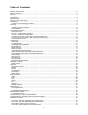
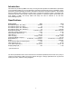
Table of Contents Warranty and Service.................................................................................................................................... 2 Table of Contents.......................................................................................................................................... 3 Warning ......................................................................................................................................................... 5 Introduction ....
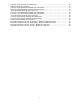
Parts List: Table Assembly (2415 Band Saw)......................................................................................... 38 Table Assembly (2013 and 2415) ........................................................................................................... 40 Parts List: Upper Wheel Base Assembly (2013 Band Saw).................................................................... 41 Parts List: Upper Wheel Base Assembly (2415 Band Saw).........................................................
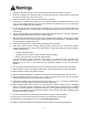
Warning 1. Read and understand the entire owners manual before attempting assembly or operation. 2. Read and understand the warnings posted on the machine and in this manual. Failure to comply with all of these warnings may cause serious injury. 3. Replace the warning labels if they become obscured or removed. 4. This band saw is designed and intended for use by properly trained and experienced personnel only.
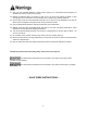
blahblahblah 21. Give your work undivided attention. Looking around, carrying on a conversation and “horse-play” are careless acts that can result in serious injury. 22. Maintain a balanced stance at all times so that you do not fall or lean against the blade or other moving parts. Do not overreach or use excessive force to perform any machine operation. 23. Use the right tool at the correct speed and feed rate. Do not force a tool or attachment to do a job for which it was not designed.
Introduction This manual is provided by WMH Tool Group covering the safe operation and maintenance procedures for a Powermatic Model 2013 or 2415 Band Saw. This manual contains instructions on installation, safety precautions, general operating procedures, maintenance instructions and parts breakdown. This machine has been designed and constructed to provide years of trouble free operation if used in accordance with instructions set forth in this manual.
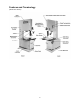
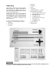
Features and Terminology (Model 2415 shown) 8
1 1 1 1 1 1 Unpacking Open shipping container and check for shipping damage. Report any damage immediately to your distributor and shipping agent. Do not discard any shipping material until the Band Saw is set up and running properly. Compare the contents of your container with the following parts list to make sure all parts are intact. Missing parts, if any, should be reported to your distributor. Read the instruction manual thoroughly for assembly, maintenance and safety instructions.
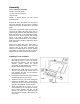
Assembly Tools required for assembly: Forklift or hoist with straps 10-12mm wrench (provided) 14mm wrench (NOTE: A socket wrench set may speed assembly time) Remove all crating and plastic from around the band saw. Remove any lag screws or holding straps which secure the band saw to the wood pallet. Use a hoist or forklift with straps to lift the band saw from the pallet. (Do NOT place forks or straps directly under the band saw table to lift it.
6. Attach the fence (D, Figure 2) to the fence body (E, Figure 2) with four 5/16 x 3/4 hex cap screws, four 5/16 lock washers, and four 5/16 flat washers. Hand tighten the screws only. 7. Place the fence assembly onto the guide rail and against the edge of the miter slot, as shown in Figure 2. The hook at the rear of the fence should fit under the rear rail (see Figure 5). 8. The fence must align parallel to the miter slot along the entire length of the fence. 9.
14. Check the clearance between the table and the fence. The fence should not rub against the table surface but be slightly above it. This gap should be the same at the front of the table as it is at the rear. See Figure 4. 15. If the gap between fence and table is not consistent, loosen either of the hex nuts on the hook (Figure 5) and rotate the sliding pad until the fence/table gap is consistent across the full length of the table. When this is achieved, tighten both hex nuts. Figure 4 16.
Check with a qualified electrician or service personnel if the grounding instructions are not completely understood, or if in doubt as to whether the tool is properly grounded. Repair or replace a damaged or worn cord immediately. Make sure the voltage of your power supply matches the specifications on the motor plate of the Band Saw. The machine should be connected to a dedicated circuit.
During hard-wiring of the Band Saw, make sure the fuses have been removed or the breakers have been tripped in the circuit to which the Band Saw will be connected. Place a warning placard on the fuse holder or circuit breaker to prevent it being turned on while the machine is being wired. Converting from 230 Volt to 460 Volt (Three Phase Only) To convert from 230 volt to 460 volt: 1. Remove the four Phillips head screws on the switch plate (Figure 8) and tilt the switch plate down.
Adjustments Table Tilt 1. Loosen the lever (Figure 10). 2. Rotate the handwheel (Figure 10) clockwise to tilt table up to 45 degrees to the right, or counterclockwise to tilt the table up to 10 degrees to the left (as viewed from the operator’s position). NOTE: If you tilt the table to the left, you must first remove the stop screw from the machine, shown in Figure 12. Figure 10 3. Tighten the lever (Figure 10).
Installing/Changing Blades Always wear gloves when handling blades. New blades are usually packaged in a coiled position; to prevent injury uncoil them slowly and carefully, while wearing gloves and safety glasses. 1. Disconnect machine from power source. 2. Decrease blade tension by rotating blade tension handwheel (A, Figure 14) according to the arrow direction in Figure 14, until the handwheel stops. Figure 13 3. Remove the table insert (Figure 13). 4.
Changes in blade width and the type of material being cut will have an effect on blade tension. Keep in mind that too little or too much blade tension can cause blade breakage and/or poor cutting performance. TIP: When the band saw is not being used, slightly release the tension on the blade – this will prolong the blade’s life. Make a note of the specific tension setting for that particular blade, as shown on the gauge (D, Figure 14).
Upper Blade Guide Assembly 1. Disconnect machine from power source. 2. Loosen lock knob (see B, Figure 14) and raise or lower upper blade guide assembly by turning the handwheel (C, Figure 14). 3. Position the blade guide assembly about 3/16” above the material to be cut. The scale (J, Figure 14) shows the distance from bottom of upper blade guides to the table surface. 4. Tighten lock knob (B, Figure 14).
12. Adjust the support bearing until it lightly contacts the dollar bill. 13. When support bearing adjustment is complete, remove dollar bill and tighten nut (E, Figure 19). Lower Blade Guides and Lower Support Bearing 1. Disconnect machine from power source. 2. Blade must already be tensioned and tracking properly. 3. Loosen two hex cap screws (J, Figure 20). 4.
Miter Gauge A miter gauge is provided for crosscutting operations. Install the miter gauge by sliding the end of the miter gauge bar into the T-slot in the table, as shown in Figure 22. To adjust the angle of the miter gauge: 1. Loosen the handle (A, Figure 22). 2. Rotate the gauge body until the pointer (B, Figure 22) lines up with the desired angle on the scale. You may have to pivot the stop (C, Figure 22) out of the way to allow the body to rotate. Figure 22 3. Tighten the handle (A, Figure 22). 4.
Belt Alignment If the drive belt is not aligned properly, it can be aligned with one or more of the four set screws located behind the steel plate. Figure 25 shows two of the set screws. 1. Loosen the four hex nuts (A, Figure 23) 2. Rotate clockwise one of the set screws (Figure 25) with a 4mm hex wrench, to push out the motor plate at that point. This will shift slightly the angle of the motor. Use whichever set screw is most effective in adjusting the angle of the motor until the drive belt is aligned.
Brake Pedal An alternate method of stopping the machine is to press the brake pedal, shown in Figure 29. The band saw will shut off when the brake pedal is pressed. The brake pedal is also useful for stopping the blade quickly, instead of waiting for the blade to coast slowly to a stop after the machine has been shut off. Re-start the saw by pressing the start button on the column. Operation Figure 29 General Procedure 1. Make sure the blade is adjusted correctly for tension and tracking. 2.
Crosscutting Crosscutting is cutting across the grain of the workpiece, while using the miter gauge to feed the workpiece into the blade. Slide the bar of the miter gauge into the end of the slot on the table. The right hand should hold the workpiece steady against the miter gauge, while the left hand pushes the miter gauge past the blade, as shown in Figure 32. Do not use the fence in conjunction with the miter gauge. The offcut of the workpiece must not be constrained during or after the cutting process.
2. Draw a line on the board parallel with the jointed, or straight edge of the board. 3. Move the band saw fence out of the way, and carefully make a freehand cut along your drawn line on the board. Stop about midway on the board, and shut off the band saw (allow the blade to come to a complete stop) but do not allow the board to move. 4. Clamp the board to the table. 5. Slide the band saw fence over against the board until it contacts the straight edge of the board at some point. Lock the fence down. 6.
Width Band saw blades come in different standard widths, measured from the back of the blade to the tip of the tooth. Generally, wider blades are used for ripping or making straight cuts, such as resawing. Narrower blades are often used when the part being cut has curves with small radii. (When cutting straight lines with a narrow blade, the blade may have a tendency to wander, causing “blade lead.”) Pitch Pitch is measured in “teeth per inch” (T.P.I.) and can be constant or variable.
Set The term “set” refers to the way in which the saw teeth are bent or positioned. Bending the teeth creates a kerf that is wider than the back of the blade. Set patterns are usually selected depending upon the type of material that needs to be cut. Three common set patterns are shown in Figure 37. Generally, the Raker set is used for cutting metal workpieces; the Wave set, when the thickness of the workpiece changes, such as cutting hollow tubing or structurals.
Maintenance Before doing maintenance, disconnect machine from electrical supply by pulling out the plug or switching off the main switch! Failure to comply may cause serious injury. Clean the band saw regularly to remove any resinous deposits and sawdust. Keep the miter slot in the table free of dust and debris. Keep the guide bearings clean and free of resin. Grease the rack and pinion system of the guide bar. Figure 38 Oil any pins, shafts, and joints. Do not get oil on the pulleys or belts. 4.
Blade Selection Guide Identify the material and thickness of your workpiece. The chart will show the recommended PITCH, blade TYPE, and FEED RATE. Key: H – Hook S – Skip R – Regular L – Low M – Medium H – High Example: 10/H/M means 10 teeth per inch / Hook Type Blade / Medium Feed For Radius Cutting Study the part drawing or prototype, or actually measure the smallest cutting radius required, and locate this radius (in inches) on the chart at the right.
Troubleshooting – Operational Problems Trouble Probable Cause Remedy Table tilt does not hold position under load. Locking lever is not tight. Tighten locking lever (see page 15). Trunnion locking mechanism is broken or worn. Replace trunnion locking mechanism. Trunnion is not lubricated. Lubricate trunnion. Trunnion is jammed. Disassemble and replace jammed parts. Incorrect blade speed. Position belt for correct speed (see page 21).
Trouble Probable Cause Remedy Blade forms cracks at base of teeth. (continued) Blade sharpened incorrectly, becomes overheated. Sharpen blade properly or replace. Band wheels have become misaligned. Contact service representative. Workpiece being fed too quickly. Reduce feed speed to lessen strain on the blade. Welding on blade not perfectly aligned. Eliminate the welded part, and reweld properly; or acquire a new blade. Support bearing is worn; caused by constant contact with back of blade.
Troubleshooting – Mechanical and Electrical Problems Trouble Machine will not start/restart or repeatedly trips circuit breaker or blows fuses. Probable Cause Remedy No incoming power. Verify machine is connected to power source. Make sure START button is pushed in completely, and the STOP button is disengaged. See page 21. Cord damaged. Replace cord. Overload automatic reset has not been reset.
Trouble Machine will not start/restart or repeatedly trips circuit breaker or blows fuses. Band Saw does not come up to speed. Probable Cause Remedy Miswiring of the unit. Double check to confirm all electrical connections are correct. Refer to appropriate wiring diagrams on pages 54 through 57 to make any needed corrections. Switch failure.
Parts List: Saw Body Assembly (2013 Band Saw) Index No. Part No. Description Size Qty 1 ...............2013-101..................Body ..................................................................... .................................... 1 2 ...............2013-102..................Magnetic Switch................................................... 1Ph, 230V ................... 1 .................2013-102CS.............Contactor Switch for 1 Phase (not shown) .......... ...............................
Parts List: Saw Body Assembly (2415 Band Saw) Index No. Part No. Description Size Qty 1 ...............2415-101..................Body ..................................................................... .................................... 1 2 ...............2415-102..................Magnetic Switch................................................... 1Ph, 230V ................... 1 .................2415-102CS.............Contactor Switch for 1 Phase (not shown) .......... ...............................
Saw Body Assembly (2013 and 2415) 35
Parts List: Table Assembly (2013 Band Saw) Index No. Part No. Description Size Qty 1 ...............2013-201..................Carriage Bolt ........................................................ 1/2”-12x9” ................... 1 2 ...............6295149 ...................Trunnion (Left Side) ............................................. .................................... 1 3 ...............2013-203..................Table Bracket ....................................................... ...............
Index No. Part No. Description Size Qty 53 .............2013-253..................Bushing ................................................................ .................................... 1 54 .............TS-0051061 .............Hex Cap Screw .................................................... 5/16”-18x1-1/4” ........... 2 56 .............TS-0270051 .............Socket Set Screw................................................. 5/16”-18x1/2” .............. 1 57 .............TS-0270061 .............
Parts List: Table Assembly (2415 Band Saw) Index No. Part No. Description Size Qty 1 ...............2013-201..................Carriage Bolt ........................................................ 1/2-12x9”..................... 1 2 ...............6295149 ...................Trunnion (Left Side) ............................................. .................................... 1 3 ...............2013-203..................Table Bracket ....................................................... ...............
Index No. Part No. Description Size Qty 53 .............2013-253..................Bushing ................................................................ .................................... 1 54 .............TS-0051061 .............Hex Cap Screw .................................................... 5/16”-18x1-1/4” ........... 2 56 .............TS-0270051 .............Socket Set Screw................................................. 5/16”-18x1/2” .............. 1 57 .............TS-0270061 .............
Table Assembly (2013 and 2415) 40
Parts List: Upper Wheel Base Assembly (2013 Band Saw) Index No. Part No. Description Size Qty 1 ...............2013-301..................Upper Wheel Shaft............................................... .................................... 1 2 ...............TS-0680091 .............Flat Washer.......................................................... 3/4”.............................. 1 4 ...............TS-0720091 .............Lock Washer ........................................................ 3/8”.....
Parts List: Upper Wheel Base Assembly (2415 Band Saw) Index No. Part No. Description Size Qty 1 ...............2013-301..................Upper Wheel Shaft............................................... .................................... 1 2 ...............TS-0680091 .............Flat Washer.......................................................... 3/4”.............................. 1 4 ...............TS-0720091 .............Lock Washer ........................................................ 3/8”.....
Upper Wheel Base Assembly (2013 and 2415) 43
Parts List: Lower Wheel Base Assembly (2013 Band Saw) Index No. Part No. Description Size Qty 1 ...............TS-0207061 .............Socket Head Cap Screw...................................... 1/4”-20x1” ................... 1 2 ...............TS-0680021 .............Flat Washer.......................................................... 1/4”.............................. 5 3 ...............6295238 ...................Brake Pedal.......................................................... ..................
Index No. Part No. Description Size Qty 53 .............TS-0720071 .............Lock Washer ........................................................ 1/4”.............................. 4 54 .............TS-081C032.............Screw ................................................................... #10-24x1/2”................. 4 55 .............TS-0720051 .............Lock Washer ........................................................ #10 .............................. 4 56 .............TS-069204 ......
Parts List: Lower Wheel Base Assembly (2415 Band Saw) Index No. Part No. Description Size Qty 1 ...............TS-0207061 .............Socket Head Cap Screw...................................... 1/4”-20x1” ................... 1 2 ...............TS-0680021 .............Flat Washer.......................................................... 1/4”.............................. 5 3 ...............6294819 ...................Brake Pedal.......................................................... ..................
Index No. Part No. Description Size Qty 53 .............TS-0720071 .............Lock Washer ........................................................ 1/4”.............................. 4 54 .............TS-081C032.............Screw ................................................................... #10-24x1/2”................. 4 55 .............TS-0720051 .............Lock Washer ........................................................ #10 .............................. 4 56 .............TS-069204 ......
Lower Wheel Base Assembly (2013 and 2415) 48
Parts List: Guide Bracket Assembly (2013 Band Saw) Index No. Part No. Description Size Qty 1 ...............6295275 ...................Guide Bar Case Bracket ...................................... .................................... 1 2 ...............6295276 ...................Cover.................................................................... .................................... 1 3 ...............TS-0081031 .............Hex Cap Screw ....................................................
Index No. Part No. Description Size Qty 55 .............6295322 ...................C-Ring .................................................................. E-5 .............................. 1 56 .............6295323 ...................Air Nozzle............................................................. .................................... 1 57 .............6295324 ...................Hose Clamp ......................................................... .................................... 1 58 ......
Parts List: Guide Bracket Assembly (2415 Band Saw) Index No. Part No. Description Size Qty 1 ...............6295275 ...................Guide Bar Case Bracket ...................................... .................................... 1 2 ...............6295276 ...................Cover.................................................................... .................................... 1 3 ...............TS-0081031 .............Hex Cap Screw ....................................................
Index No. Part No. Description Size Qty 55 .............6295322 ...................C-Ring .................................................................. E-5 .............................. 1 56 .............6295323 ...................Air Nozzle............................................................. .................................... 1 57 .............6295324 ...................Hose Clamp ......................................................... .................................... 1 58 ......
Guide Bracket Assembly (2013 and 2415) 53
Electrical Connections: 230 Volt, Single Phase – Model 2013 Band Saw ONLY 2013 Band Saw ONLY 54
Electrical Connections: 230 Volt, Single Phase – Model 2415 Band Saw ONLY 2415 Band Saw ONLY 55
Electrical Connections: 230 Volt, 3 Phase – Models 2013 and 2415 56
Electrical Connections: 460 Volt, 3 Phase – Models 2013 and 2415 57
NOTES 58
WMH Tool Group 2420 Vantage Drive Elgin, Illinois 60123 Phone: 800-274-6848 www.wmhtoolgroup.