Operating Instructions and Parts Manual 18-inch Variable Speed Drill Press Model 2800 WMH TOOL GROUP 2420 Vantage Drive Elgin, Illinois 60124 Ph.: 800-274-6848 www.wmhtoolgroup.com Part No.
Warranty and Service WMH Tool Group, Inc., warrants every product it sells. If one of our tools needs service or repair, one of our Authorized Service Centers located throughout the United States can give you quick service. In most cases, any of these WMH Tool Group Authorized Service Centers can authorize warranty repair, assist you in obtaining parts, or perform routine maintenance and major repair on your POWERMATIC® tools. For the name of an Authorized Service Center in your area call 1-800-274-6848.
Table of Contents Warranty and Service .............................................................................................................................. 2 Table of Contents .................................................................................................................................... 3 Warning................................................................................................................................................... 4 Introduction .....................
Warning 1. Read and understand the entire owners manual before attempting assembly or operation. 2. Read and understand the warnings posted on the machine and in this manual. Failure to comply with all of these warnings may cause serious injury. 3. Replace the warning labels if they become obscured or removed. 4. This drill press is designed and intended for use by properly trained and experienced personnel only.
21. Give your work undivided attention. Looking around, carrying on a conversation and “horse-play” are careless acts that can result in serious injury. 22. Maintain a balanced stance at all times so that you do not fall or lean against the drill bit or other moving parts. Do not overreach or use excessive force to perform any machine operation. 23. Use the right tool at the correct speed and feed rate. Do not force a tool or attachment to do a job for which it was not designed.
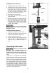
Introduction This manual is provided by WMH Tool Group covering the safe operation and maintenance procedures for a Powermatic Model 2800 Drill Press. This manual contains instructions on installation, safety precautions, general operating procedures, maintenance instructions and parts breakdown. This machine has been designed and constructed to provide years of trouble free operation if used in accordance with instructions set forth in this manual.
The smaller accessories are shown in Figure 1: 3 Downfeed Handles (A) 1 Chuck (B) 1 Drift Key (C) 1 Arbor (D) 1 Shift Knob (E) 1 Locking Handle (F) 2 Lock Knobs (G) 2 T-Nuts (G) 2 Flat Washers (G) 2 Socket Head Cap Screws, M6x12 (G) 2 Hex Nuts, M6 (G) 1 Worm (H) 1 Large Handle (I) 4 Hex Cap Screws, M10x40 (J) 3 Hex Wrenches, 3,5 and 6mm (K) 1 Dust Port (L) 1 Fence Assembly (M) 1 Owner's Manual (not shown) 1 Warranty Card (not shown) Unpacking Open shipping container and check for shipping damage.
Assembly Tools required for assembly: Cross-point (Phillips) screwdriver Rubber mallet Wrenches – 17, 18 and 24 mm Set of hex (Allen) wrenches Exposed metal surfaces on the drill press have been factory-coated with a protectant. Remove this with a soft rag moistened with kerosene or a light solvent. Do not use an abrasive pad and do not use gasoline, paint thinner or acetone, as these will damage plastic components and painted surfaces.
3. Slide the large handle onto the spindle of the table bracket (Figure 4), and tighten the set screw in the handle with a 3mm hex wrench. Crank the handle counterclockwise to lower the table bracket down the column. 4. Place the ring onto the column and slide it down over the top edge of the rack (see Figure 3). Tighten the set screw on the ring. 5. Screw the locking handle into the table bracket (Figure 4) and tighten the locking handle to secure the table bracket’s position on the column.
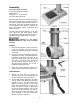
Installing Arbor and Chuck 1. Disconnect machine from power source. 2. Thoroughly clean the entire arbor and the inside of the chuck (Figure 9) with a soft rag and solvent such as mineral spirits. Any grease or residue in these areas can cause the pieces to separate and create a safety hazard as well as damage to the tool. 3. Slide arbor up into the spindle. 4. Firmly push the chuck by hand onto the taper of the arbor. 5.
Improper connection of the equipmentgrounding conductor can result in a risk of electric shock. The conductor with insulation having an outer surface that is green with or without yellow stripes is the equipmentgrounding connector. If repair or replacement of the electric cord or plug is necessary, do not connect the equipment-grounding conductor to a live terminal.
4. The drill press must comply with all local and national codes after the 230 volt plug is installed. Recommended Gauges (AWG) of Extension Cords Extension Cord Length * 5. The drill press with a 230-volt plug should only be connected to an outlet having the same configuration as shown in Figure 13. No adapter is available or should be used with the 230-volt plug.
Table Extensions Loosen the handles (C, Figure 15) and slide the extensions outward, then re-tighten the handles. Changing Spindle Speeds Change speeds only while the drill press is running. With the drill press running, rotate the shift knob (Figure 17) slightly counterclockwise to loosen it, then push the handle left or right until the desired speed is displayed on the LED readout at the front of the head. Tighten the shift knob clockwise to secure the setting.
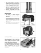
6. Make sure the coil spring cover is pushed back in, then tighten the two hex nuts (D). Do not over tighten. The hex nuts should be tightened against each other. 7. Re-install hub, washers, hex nut and cap. On/Off Switch Pull out the switch to start the drill press, push to stop. The switch has a safety feature that prevents unauthorized or accidental starting of the drill press. With the switch in the "off" position, slide out the switch safety key (Figure 20).
Repeat step 5, if necessary, until the light and marking are aligned. 6. Adjust the other laser in the same manner. Two parallel laser markings should look like O and P in Figure 22 – the distance between the lines will vary with board thickness; however, the lines must be parallel. Cross Hair Alignment 7. Place board (R) flat on the table. Do not allow the board to move from this position; use clamps if needed. Bring the bit down until it leaves a slight perforation in the board; then raise it back up. 8.
Maintenance condition and tensioned properly. Occasional dressing of the belts with spray can type belt dressing or paraffin wax will promote longer belt life and quieter operation. Before doing maintenance on the machine, disconnect it from the electrical supply by pulling out the plug or switching off the main switch! Failure to comply may cause serious injury. Bearings on the drill press are self-contained and permanently lubricated; no further lubrication is needed.
Trouble Probable Cause Remedy Noisy Operation (cont.) Noisy motor. Check motor bearings or for loose motor fan. Wood splinters on the underside. No backing board used. Place a scrap board beneath the workpiece to prevent splintering. Excessive speed. Reduce speed. Chips not clearing from hole or bit. Retract drill bit frequently to remove chips. Dull drill bit. Resharpen, or replace drill bit. Feeding the bit too slowly. Increase feed rate. Rotation of bit incorrect.
Model 2800 Drill Press 18
Parts List: Model 2800 Drill Press Index No. Part No. Description Size Qty 1............... PM2800-001 ............Strain Relief........................................................................................... 2 2............... TS-1482051 .............Hex Cap Screw ..................................................M6x25 ........................ 4 3............... PM2800-003 ............Retaining Plate ...................................................................................... 1 4..
57............. PM2800-057 ............Rack Ring.............................................................................................. 1 58............. PM2800-058 ............Lead Wire Assembly...........................................26AWG*2C-550MM.... 2 59............. PM2800-059 ............Locking Cable Tie...............................................A-085S ...................... 1 60............. PM2800-060 ............Gear....................................................................
117........... PM2800-117 ............Bracket.................................................................................................. 1 118........... PM2800-118 ............Washer.................................................................................................. 1 119........... PM2800-119 ............Stop Nut .............................................................M16............................ 2 120........... PM2800-120 ............Depth Stop Bolt & Scale Assembly ........
178........... TS-152706...............Hex Wrench .......................................................5 mm.......................... 1 179........... TS-152707...............Hex Wrench. ......................................................6 mm.......................... 1 180........... PM2800-180 ............Power Cord ........................................................14AWGx3C ................ 1 181........... PM2800-181 ............Retaining Ring...................................................
Electrical Connections 23
Electrical Connections 24