Operating Instructions and Parts Manual Vertical Panel Saw Model 511 WMH TOOL GROUP 2420 Vantage Drive Elgin, Illinois 60123 Ph.: 800-274-6848 www.wmhtoolgroup.com Part No.
This manual has been prepared for the owner and operators of a Powermatic Model 511 Panel Saw. Its purpose, aside from machine operation, is to promote safety using accepted operating and maintenance procedures. To obtain maximum life and efficiency from your panel saw and to aid in using it safely, please read this manual thoroughly and follow the instructions carefully. Warranty and Service WMH Tool Group warrants every product it sells.
Table of Contents Warranty and Service ..............................................................................................................................2 Warning...................................................................................................................................................4 General Operating Instructions.................................................................................................................7 Operating Tips..............................
Warning 1. Read and understand the entire owners manual before attempting assembly or operation. 2. Read and understand the warnings posted on the machine and in this manual. Failure to comply with all of these warnings may cause serious injury. 3. Replace the warning labels if they become obscured or removed. 4. This panel saw is designed and intended for use by properly trained and experienced personnel only.
blahblahblah 20. Make your workshop child proof with padlocks, master switches or by removing starter keys. 21. Give your work undivided attention. Looking around, carrying on a conversation and “horse-play” are careless acts that can result in serious injury. 22. Maintain a balanced stance at all times so that you do not fall or lean against the blade or other moving parts. Do not overreach or use excessive force to perform any machine operation. 23. Use the right tool at the correct speed and feed rate.
Familiarize yourself with the location and content of these decals on your machine.
General Operating Instructions The suggestions listed below are meant to give you a general idea of how your new Panel Saw is intended to be operated. No amount of instruction can replace good common sense and experience. Be sure the operators of your new Panel Saw are given enough time and material to become familiar with the general operating characteristics of this machine and have FULLY READ AND UNDERSTAND all general operating and safety instructions. The panel saw is prealigned at the factory.
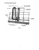
511 Panel Saw Features 8
Introduction This manual is provided by Powermatic covering the safe operation and maintenance procedures for a Model 511 Vertical Panel Saw. This manual contains instructions on installation, safety precautions, general operating procedures, maintenance instructions and parts breakdown. This machine has been designed and constructed to provide years of trouble free operation if used in accordance with instructions set forth in this manual.
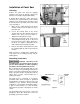
Installation of Panel Saw Uncrating Remove the panel saw from the shipping container and check for damage. Report any damage to the freight company immediately. A wooden block and three cables have been fastened to the counterweight to secure it during shipment. This wooden block and cables must be removed before operation of the saw. Follow steps 1 through 4: Figure 3 1. Make sure the cable attached to the motor carriage is placed over the pulley on top of the panel saw. 2.
The green wire must be the only wire connected to the machine’s grounding system and must never be attached to an electrically “live” terminal. A temporary adapter, shown in Figure 6, can be used to connect a grounded plug to a two-prong outlet. The green rigid ear or lug extending from the adapter must be connected to a permanent ground such as a properly grounded outlet box or receptacle.
Operating Tips 1. Use industrial carbide saw blades that are sharp. Dull blades may cause chipping, chatter or overloading of the motor. If you’re not sure whether a blade is sharp, replace it with a new one. 2. Feed material through the saw (ripping) or lower the carriage (crosscutting) slowly, smoothly and whenever possible without stopping. Overfeeding can result in poor quality cuts, shorten the life of the blade, and overload the motor. 3.
5. Slide workpiece into position against the adjustable stop, while double checking the cut size via the crosscut rulers. Make sure workpiece is adequately supported. Use one hand to guide it. Do not hold workpiece so that your hand is behind the carriage or guides or near the path of the blade. 6. Start motor and allow it to reach full speed. 7. Pull carriage down slowly and smoothly as the blade moves through the workpiece. Keep one hand on the handle at all times and do not force the saw.
3. Select height of saw blade above the rollers. Move the carriage until the index tab is aligned with the corresponding dimension on the vertical ruler. Lock the carriage securely to the guides with the locking knob. 4. Start motor and allow it to reach full speed. 5. Place workpiece on the side of machine according to direction of cut shown by the arrow on the carriage. DO NOT DROP workpiece on rollers. 6. With the motor at full speed, move the workpiece slowly and smoothly through the saw.
3. Engage spindle lock (Figure 14) on the motor to keep spindle from turning. Use the wrench provided to loosen and remove the arbor bolt (NOTE: left hand threads, turn clockwise to loosen). See Figure 15. 4. Remove outer flange, blade, and inner flange. See Figure 15. 5. Clean spindle, flanges, bolts and blade to remove dust and debris. 6. Re-install inner flange, and install new blade with arrow pointing as shown in Figure 15. Reinstall outer flange and tighten arbor bolt with wrench. 7.
Alignment If the saw ever needs realignment, it should be performed in the following order: 1. Align rollers. 2. Align guides perpendicular to rollers. 3. Align blade parallel to guides. To ensure accuracy over the full movement of the saw, construct a test square as follows, (Figure 17): Use a 6-foot metal ruler and two 4-foot metal rulers (using the 3-, 4-, and 5-ft. measurements ensures squareness). Drill holes and attach the rulers with pop rivets or small nuts and bolts.
Step 2: Align Guides Disconnect saw from power source before aligning the guides. If the saw does not cut at 90 degrees, the guides may not be perpendicular to the rollers. Adjust as follows: 1. Make sure the rollers are aligned. 2. Remove the blade guard and mark a blade tooth as a reference (NOTE: If the saw has a high speed steel blade, mark a tooth that points toward the edge of your test square, which is still clamped above the rollers.) 3.
6. Loosen, but do not remove, the two nuts holding the indexing pin assembly. See Figure 21. 7. If burn marks appear on the left side of the workpiece, rotate saw clockwise until entire face of blade contacts your straightedge. If burn marks appear on the right side of workpiece, rotate saw counterclockwise until entire face of blade contacts your straightedge. 8. Retighten assembly. nuts holding indexing pin 9. Make a test cut and further adjustments if necessary.
Periodically: 1. The carriage is designed to move smoothly along the guide tubes. If the guide tubes become caked with dust, the carriage may not slide evenly or become stuck. Occasionally clean the guide tubes with a damp cloth and apply a dry lubricant such as a spray silicone. 2. Rotate the motor to horizontal position and check the motor oil level at the plug. Figure 22 shows the location of the oil plug. If low, fill with SAE 70 or 80 gear oil to proper level.
Replacement Parts Replacements parts are listed on the following pages.To order parts or reach our service department, call 1-800-274-6848 between 7:30 a.m. and 6:00 p.m. (CST), Monday through Friday. Having the Model Number and Serial Number of your machine available when you call will allow us to serve you quickly and accurately.
Parts List: 511 Panel Saw Index No. Part No. Description Size Qty ................ 2078021 ..................Carriage Assembly (Items 15, 17 & 24) .............. .................................. 1 1 ............. 2218033 ..................Frame Assembly ................................................ .................................. 1 2 ............. 2423020 ..................Leg Assembly .................................................... .................................. 1 3 .............
Index No. Part No. Description Size Qty 56 ............ 6813142 ..................Spring ................................................................ .................................. 1 57 ............ 6430050 ..................Locking Knob ..................................................... .................................. 1 58 ............ 6716218 ..................Hex Head Screw ................................................3/8-16 X 5 .................. 1 59 ............ 2063181 ..........
Index No. Part No. Description Size Qty 117 .......... 6940064 ..................Cable Tie ........................................................... .................................. 7 118 .......... JW1317 ...................Hose Clamp .......................................................4" (2-Ring).................. 1 119 .......... JW1015 ...................Y Fitting..............................................................4" ............................... 1 120 .......... JW1022 ..........
511 Panel Saw refer to parts list, pages 21-23 24
511 Panel Saw, Motor with Pushbutton Assembly 2475002 refer to parts list, pages 21-23 26
511 Panel Saw Dust Collection System refer to parts list, pages 21-23 27
Electrical Connections refer to parts list, pages 21-23 28
S-B Factory Service Centers for the Skil worm drive motor 800-815-8665 ST SC# CITY TELEPHONE# ADDRESS ZIP FAX# MANAGER AZ CA KS 77 41 2 26 79 48 60 39 3 43 4 25 47 24 64 (602) 272-1121 (714) 630-3244 (909) 390-8877 (916) 451-8473 (619) 268-8335 (408) 727-9444 (303) 893-5123 (904) 398-0728 (305) 624-9011 (813) 289-3770 (770) 452-8192 (808) 848-8665 (773) 774-0600 (630) 543-8660 (913) 381-3883 2729 W. McDowell Road 1290 N.
Parts List: Skilsaw, Model 586, Type 2 (511 Panel Saw) NOTE: For all parts and service on the Skil worm drive motor, please contact the Skil service center near you from the list on page 29. Index No. Part No. Description Powermatic Part No. 1 ...............325089 .............Bearing Cover 2 ...............23331 ...............Washer 3 ...............23324 ...............Lock Pin Bushing 5 ...............325655 .............Lock Pin 6 ...............44638 ...............“O” Ring1 7 ...............
Index No. Part No. Description Powermatic Part No. 54 ..............320881 .............Cord and Plug 55 ..............5970.................Strain Relief 56 ..............27039 ...............Set Screw (2) 57 ..............320391 .............Brush and Spring (2).....................6861260 58 ..............306278 .............Brush Cap (2) ...............................6861261 59 ..............315286 .............Stud3 60 ..............350005 .............Plug Button 61 ..............23334 ............
Short Panel Fence (Optional Accessory) The Short Panel Fence is designed as an aid in cutting short panels by bringing the panel up to waist height. The Fence fits on both the left and right sides of the panel saw which gives support when cutting. Figure 23 shows the components of the Short Panel Fence. Part No. Description Size Qty. 2721005....... Short Panel Fence Shelf Assembly 3064729....... Short Panel Fence Bracket R.H............................................. ..................................
Step 2: Step 6: With a power drill, attach the fence bracket to the vertical cross members with the mounting screws provided. The mounting screws provided are self-tapping. (Note: The fence bracket is pre-drilled for mounting.) Place the fence shelf between the bracket and the top of the round bushings with the black molding showing. If the shelf is not a snug fit, remove the shelf, loosen the bushing mounting bolts, press up on the bushing, retighten the mounting bolts and re-install the shelf.
Optional Accessories Part No. Description 2721005 ....... Short Panel Fence Shelf Assembly 6080149 ....... CMT Saw Blade 6080150 ....... Amana Saw Blade 6819003 ....... Adjustable Stop (RH) 6819004 ....... Adjustable Stop (LH) Adjustable Stop (Optional Accessory) The Adjustable Stop has a 66” scale and is available in right hand or left hand versions. It mounts to the bottom rail of the panel saw as shown.
WMH Tool Group 2420 Vantage Drive Elgin, Illinois 60123 Phone: 800-274-6848 www.wmhtoolgroup.