
Use and Care Manual


Powermatic
427 New Sanford Road
LaVergne, Tennessee 37086 Part No. M-6294721
Ph.: 800-274-6848 Edition 2 01/2016
www.powermatic.com Copyright © 2015 Powermatic, a division of JPW Industries
#6294721, TAILSTOCK SWING AWAY
WARNING – To reduce the risk of serious injury:
• Read and understand all instructions and warnings in lathe manual and Swing Away instructions before operating.
• Replace warning labels if they become obscured or removed.
• Always wear eye protection.
• Tighten knob on Swing Away before using lathe. Knob must remain tightened while Swing Away is in upright position.
• Securely tighten tailstock clamp handle before moving Swing Away.
• Do not allow Swing Away to swing freely; maintain firm grasp on Swing Away throughout movement.
• Keep fingers away from pivot pin area while moving Swing Away.
• Never release tailstock clamp handle unless Swing Away is in upright position with knob tightened.
• Failure to comply with the above warnings may result in serious or even fatal injury, or damage to machine.
NOTE: This accessory is intended only for use with
Powermatic models 3520, 3520A, 3520B, PM2020 Lathes.
Contents of container:
1 Swing Away
2 Socket head cap screws, 3/8 x 1-1/4 in.
2 Lock washers, 3/8 in.
4 Flat washers, 3/8 in.
2 Hex nuts, 3/8 in.
1 Instruction sheet
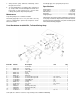
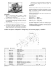
Assembly
Refer to parts breakdown for any assembly clarification.
Numbers in parentheses refer to index numbers in parts list.
1. Make sure threaded holes in end of lathe bed are clean.
2. Confirm proper clearance around lathe for Swing Away
function.
3. Remove stop bolt from lathe bed and store for future use.
(NOTE: Always reinstall stop bolt when tailstock is on
lathe bed and Swing Away is not engaged.)
4. Mount Swing Away to lathe bed with provided screws and
washers (#9/10/11, Figure 1). Do not tighten yet.
(* For model 3520 Lathes, see special instructions.)
5. Align top surface of Swing Away with lathe bed ways.
(Use a straight edge to check.) Loosen knob and open
Swing Away; turn set screws (#13) as needed to help
achieve parallelism.
6. When properly aligned, firmly tighten screws (#9), and
close Swing Away. Tighten knob. (Knob is under spring
pressure – push in while rotating.)
7. Slide tailstock onto Swing Away, and check for smooth
transition of tailstock across joint. Make further
adjustments as needed until tailstock transitions
smoothly. When done, make sure screws (#9) are
securely tightened.
Figure 1
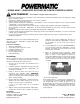
* For model 3520 Lathes:
Two additional flat washers (#11) and hex nuts (#17) are
provided for securing Swing Away to model 3520 Lathe. See
parts breakdown. When positioning model 3520 tailstock onto
Swing Away, compensate for increased bed thickness by
adjusting lock nut beneath tailstock (Figure 2).
Figure 2: for model 3520 only
Operation
1. Slide tailstock onto Swing Away, and securely tighten
tailstock clamp handle.
2. Grasp tailstock handwheel with one hand and slightly
push toward lathe to relieve pressure on Swing Away.
Loosen knob with other hand.