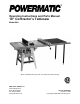
Operating Instructions and Parts Manual 10” Contractor’s Tablesaw Model 64A Model 1791228K shown (50” rails, wood extension table and legs) WMH TOOL GROUP, Inc. 2420 Vantage Drive Elgin, Illinois 60124 Ph.: 800-274-6848 www.powermatic.com Part No. M-0460250 Revision H 3/08 Copyright © 2008 WMH Tool Group, Inc.
Warranty and Service WMH Tool Group, Inc., warrants every product it sells. If one of our tools needs service or repair, one of our Authorized Service Centers located throughout the United States can give you quick service. In most cases, any of these WMH Tool Group Authorized Service Centers can authorize warranty repair, assist you in obtaining parts, or perform routine maintenance and major repair on your POWERMATIC® tools. For the name of an Authorized Service Center in your area call 1-800-274-6848.
Table of Contents Warranty and Service .............................................................................................................................. 2 Table of Contents .................................................................................................................................... 3 Warning................................................................................................................................................... 4 Introduction .....................
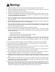
Warning 1. Read and understand the entire owner’s manual before attempting assembly or operation. 2. Read and understand the warnings posted on the machine and in this manual. Failure to comply with all of these warnings may cause serious injury. 3. Replace the warning labels if they become obscured or removed. 4. This table saw is designed and intended for use by properly trained and experienced personnel only.
19. Be sure the saw blade rotates clockwise when viewed from the motor side (left side) of the machine. 20. Do not attempt to saw boards with loose knots or with nails or other foreign material, on its surface. Do not attempt to saw twisted, warped, bowed or “in wind” stock unless one edge has been jointed for guiding purposes prior to sawing. Do not attempt to saw long or wide boards unsupported where spring or weight could cause the board to shift position. 21. Remove adjusting keys and wrenches.
Introduction This manual is provided by WMH Tool Group, Inc. covering the safe operation and maintenance procedures for a Powermatic Model 64A 10” Tablesaw. This manual contains instructions on installation, safety precautions, general operating procedures, maintenance instructions and parts breakdown. This machine has been designed and constructed to provide years of trouble free operation if used in accordance with instructions set forth in this manual.
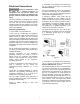
2. Grounded, cord-connected tools intended for use on a supply circuit having a nominal rating less than 150 volts: Electrical Connections Electrical connections must be made by a qualified electrician in compliance with all relevant codes. This machine must be properly grounded to help prevent electrical shock and possible fatal injury. This tool is intended for use on a circuit that has an outlet that looks like the one illustrated in Figure 1(A).
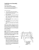
230 Volt Conversion If 230V single phase operation is desired, follow these instructions: 1. Disconnect tablesaw from power source. 2. Open the motor junction box, and consult the diagrams affixed to the inside of the junction box cover. These diagrams are also shown in Figures 2 and 3. This saw is supplied with four motor leads that are connected for 115V operation (Figure 2). Reconnect these four motor leads for 230V operation (Figure 3). 3.
1 1 1 1 1 1 1 2 2 1 1 1 1 2 5 1 1 Unpacking Open shipping container and check for shipping damage. Report any damage immediately to your distributor and shipping agent. Do not discard any shipping material until the Tablesaw is assembled and running properly. Compare the contents of your container with the following parts list to make sure all parts are intact. Missing parts, if any, should be reported to your distributor.
Installation and Assembly Tools required: Arbor wrench (supplied) 12mm combination wrench (supplied) 3mm and 4mm hex wrenches (supplied) 8, 10, 14, 15, and 19 mm open-end wrenches Cross point and flat head screwdrivers Some assembly tips: 1. A bowl should be used to hold hardware. 2. To avoid harming the table saw top, a cloth should be placed on the floor first. 3. Do not remove wax coating from table until saw is assembled. 4. Start assembly in the area where saw will be used.
2. Attach the four short braces to one set of legs as shown in Figure 6. 3. Complete the stand assembly by attaching the other set of legs as shown in Figure 7. 4. To attach rubber feet to each leg, first use a cross-point screwdriver and screw the 1/420 x 1 pan head screw through the recessed hole of the rubber grommet as shown in Figure 8. Push the screw through the hole provided at the bottom of each leg, and tightly fasten down with 1/4 flat washer and 1/4 hex nut. 5.
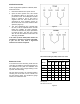
Handwheels and Lock Knobs 1. Attach handwheel knob (A) by inserting screw (B) through hollow knob and into the 3/8" lock nut (C). See Figure 10. Lightly screw assembly into handwheel. 2. Tighten the nut (C) to the handwheel just enough so that there is adequate looseness in the knob (A) to allow free rotation. 3. Attach the elevating and tilting handwheels with lock knobs to the elevating and tilting screws on the machine, as shown in Figure 10.
6. Install the motor assembly onto the protruding studs at the back of the saw. See Figure 15. 7. Tighten down setscrews in top of cast motor bracket with hex wrench as shown in Figure 15. 8. Use an assistant or get a support block (for example, a 2x4) approximately 21" to 22" long. Lift motor up and position block under the motor to support its weight. 9. Slightly loosen motor base screws. 10. Confirm belt alignment using a straight edge as shown in Figure 16.
Mounting Blade Guard and Splitter 1. Disconnect saw from power source. 2. Attach splitter mounting bracket to saw trunnion using pin, nut and washer as shown in Figure 18. Insert the pin into the trunnion hole until it is flush on the other side, then hold a wrench on the flat of the pin to stabilize it, while tightening the nut counterclockwise. The upper bracket is secured to the lower bracket with four 5/1618 x 1 screws, four 5/16 flat washers, and four 5/16 hex nuts. Figure 18 3.
Mounting Table Insert 1. Place the table insert into the table opening. With a straight edge, check to see if the insert is level with the surface of the table. See Figure 22. 2. If the insert is not level, correct it by using the straight edge and turning the four set screws in or out until the insert is flush with the table. Mounting Extension Wings Figure 22 TIP: Use WD-40® to clean table edges. 1.
Installing Dust Shroud TIP: Since the dust shroud is installed from beneath, aid from a helper to install the screws and tabs will make this task much easier. 1. From under the saw, position the dust shroud at an angle to go through the opening between the stand and the saw. Set the lip of the shroud to sit on the top side of the stand as shown in Figure 24. 2.
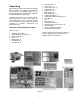
Dado Insert Dadoing is cutting a rabbet or a wide groove into the workpiece. The dado insert, shown in Figure 27, is included as standard equipment with your saw. Rotate the set screws as needed to level the dado insert with table surface. Do not use the standard table insert for dadoing operations. Adjustments power source adjustments. Disconnect motor before making from any Figure 27 Blade Adjustment 1.
45 and 90 Degree Positive Stops Convenient access to these adjustments will be from the back side of the saw. 1. Disconnect machine from power source. 2. Raise the saw blade to its maximum height. 3. Set the blade at 90 degrees to the table by turning the blade tilting handwheel clockwise as far as it will go. 4. Place a square on the table and check to see that the blade is at a 90 degree angle to the table. See Figure 30. Figure 30 5.
3. If it does not, loosen lock handle (B - Figure 32). 4. Loosen locknut (E), and adjust the stop screw, (A), so it strikes the stop link (D) when the gauge is at 90 degrees. 5. Retighten both the locknut (E) and lock handle (B). Figure 33 Aligning Splitter to Blade The splitter assembly must be aligned with the saw blade to help prevent kickback. 1. Lay a straight edge against the saw blade and the splitter as shown in Figure 34. 2.
Basic Saw Operation 1. Familiarize yourself with the location and operation of all controls and adjustments and the use of the mitre gauge and rip fence. 2. Serious injury can result from kickbacks which occur when a workpiece binds on the saw blade or binds between the saw blade and rip fence or other fixed objects. This binding can cause the workpiece to lift up and be thrown toward the operator. Listed below are the conditions which can cause kickback and should be thoroughly familiar to the operator.
• Check the operation of the anti-kickback pawls before starting a cut. If the pawls do not stop the reverse motion of a workpiece, resharpen all the points. • Keep your face and body out of line with potential kickbacks when possible, including when starting or stopping the machine. 3. Dull or improperly sharpened blades and blades with gum or resin adhering to them may cause an accident with the tilting arbor saw. Never use a cracked saw blade.
3. Never rip freehand or use the miter gauge in combination with the fence. Never rip workpieces shorter than the blade diameter without a push stick. Never remove the cutoff piece with the saw blade rotating. 4. Always use the saw guard, splitter and antikickback pawls and make sure the splitter is properly aligned. When wood is cut along the grain, the kerf tends to close and bind the blade and kickbacks can occur.
Resawing 1. Resawing is a ripping operation in which thick boards are cut into thinner ones. Narrow boards up to 3" can be resawn in one pass. Wider boards up to 6" must be resawn in two passes. 2. In resawing wider boards, adjust the blade height so as to overlap the two cuts by 1/2" (Figure 40). Too deep a first cut can result in binding and kickbacks on the second cut. Always use the same side of the board against the fence for both cuts. Crosscutting Figure 40 1.
7. Provide auxiliary support for any workpiece which tends to sag and lift up off the table when it extends beyond the table top. 8. Have the blade extend about 1/8" above the top of the workpiece. Exposing the blade above this point can be hazardous. Bevel and Miter Operations 1. A bevel cut is a special type of operation where the saw blade is tilted at an angle less than 90 degrees to the table top. Operations are to be performed in the same manner as ripping or crosscutting.
Never use a wedge between arbor collar and saw blade to create a "wobble" dado. Never operate the saw without guard, splitter and anti-kickback pawls for operations where they can be used. Never use a dado head in tilted position. SAFETY DEVICES Feather Board (Figure 46) The Feather Board is to be made of straight grain hardwood approximately 1” thick and 4" to 8" wide. The length is developed in accordance with intended use. Feather Boards can be fastened to the table or rip fence by use of “C” clamps.
trunnions, grease these three areas with a good grade non-hardening grease. Maintenance 3. The table surface must be kept clean and free of rust for best results. An occasional coat of paste wax on the table will allow the wood stock to glide smoothly across the work surface. Before doing maintenance on the machine, disconnect it from the electrical supply by pulling out the plug or switching off the main switch! Failure to comply may cause serious injury.
Troubleshooting Trouble Tablesaw will not start. Excessive vibration. Cuts out-of-square when crosscutting. Motor stalls or workpiece binds or burns. Cuts not true at 90 or 45 degrees. Tilting or Raising handwheel difficult to turn. Probable Cause Remedy No incoming power. Check all plug connections. Fuse blown, or circuit breaker tripped. Replace fuse, or reset circuit breaker. Cord damaged. Replace cord. Tilting or Raising lock knobs not tightened. Tighten lock knobs on handwheels.
Trouble Motor starts slowly or fails to come up to full speed. Motor fails to develop full power. Probable Cause Remedy Low voltage. Request voltage check from power company and correct low voltage condition. Centrifugal switch not operating. Replace centrifugal switch (qualified personnel only). Motor malfunction. Have motor checked by a qualified inspector. Repair or replace. Power line overloaded. Correct overload condition. Undersized wires in supply system. Increase supply wire size.
Parts List: Table Saw, Extension Wings and Guard Index No. Part No. Description Size Qty 1............... 6290694...................Table Insert ........................................................................................... 1 1-A ........... 6291342...................Rubber spacer....................................................................................... 2 2............... 6290695...................Dado Insert......................................................................
66............. 6291335...................Nut .....................................................................3/16-24....................... 2 67............. 6291366...................Switch Box ............................................................................................ 1 68............. 6291367...................Switch Bracket....................................................................................... 1 69............. 6291368...................Switch .....................
Parts List: Stand Assembly Index No. Part No. Description Size Qty 1............... 6290646...................Leg........................................................................................................ 4 2............... 6290650...................Bottom Long Bracket ............................................................................. 2 3............... 6290648...................Bottom Short Bracket............................................................................. 2 4.
Parts List: Motor and Trunnion Assembly Index No. Part No. Description Size Qty 1............... 6290563...................Knob ..................................................................................................... 2 2............... 6290565...................Handle................................................................................................... 2 3............... 6290566...................Nut, Hex Hd........................................................3/8-16.........
74............. 6291325...................Fiber Washer......................................................5/16............................ 2 75............. 6285540...................Wing Nut ............................................................5/16-18....................... 2 76............. 6290642...................Wrench...............................................................#23............................. 1 77............. 6290643...................Wrench...............................
Motor and Trunnion Assembly 34
WMH Tool Group, Inc. 2420 Vantage Drive Elgin, Illinois 60124 Phone: 800-274-6848 www.powermatic.com www.wmhtoolgroup.