20" WOODTURNING LATHE Model 3520A Instruction Manual & Parts List M-0460221 (800) 248-0144 www.powermatic.
This manual has been prepared for the owner and operators of a Powermatic Model 3520A Lathe. Its purpose, aside from proper machine operation, is to promote safety through the use of accepted correct operating and maintenance procedures. Completely read the safety and maintenance instructions before operating or servicing the machine. To obtain maximum life and efficiency from your lathe, and to aid in using the machine safely, read this manual thoroughly and follow all instructions carefully.
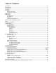
TABLE OF CONTENTS Safety Rules.........................................................................................................................................4-5 Safety: Decals ......................................................................................................................................... 6 Specifications .......................................................................................................................................... 7 Receiving ....................
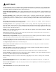
! SAFETY RULES As with all machines, there is a certain amount of hazard involved with the use of this lathe. Use the machine with the respect and caution demanded where safety precautions are concerned. When normal safety precautions are overlooked or ignored, personal injury to the operator can result. Read, understand and follow the safety and operating instructions found in this manual. Know the limitations and hazards associated with this machine.
Do not attempt to engage the spindle lock pin until the spindle has stopped. If leaving the machine area, turn it off and wait until the spindle stops before departing. Give the work you are doing your undivided attention. Looking around, carrying on a conversation and "horseplay" are careless acts that can result in serious injury.
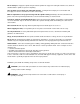
! SAFETY: DECALS Familiarize yourself with the location and content of this decal on your machine.
SPECIFICATIONS: 3520A Lathe Table with standard extensions..................................................................................................................... 28” x 38” Distance Between Centers............................................................................................................................. 34-1/2" Swing Over Bed ....................................................................................................................................................
RECEIVING Remove the lathe from the shipping container and check for damage. Report any damage to your distributor immediately. Accessories are packaged in a separate carton which will be on the shelf of the machine stand. Clean protective coating from the bed, spindles, work rest and face plate with kerosene or a good commercial solvent. Read the instruction manual thoroughly for assembly, maintenance, operation and safety instructions.
Tool Support Speed Range Adjustment The tool support (shown in Figure 5), is designed to allow adjustment for height, position on the bed, and angle to the work. Your 3520A lathe comes standard with the 14" tool support. Other supports are available; consult the "Optional Equipment" list on page 24. Periodically the tool rest should be disassembled and the parts cleaned and oiled to provide free movement of the parts to insure good clamp action.
TOOLS If possible, select only quality, high speed steel turning tools. High speed tools hold an edge and last longer than ordinary carbon steel. As one becomes proficient in turning, a variety of specialty tools for specific applications can be acquired. The following tools provide the basics for most woodturning projects: Large Roughing Gouge - 1" to 1-1/4", used to eliminate waste wood. Skews - 1-1/2" and 1" or 1-1/4", used to make finishing cuts and details.
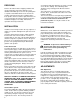
SPINDLE TURNING Spindle turning takes place between the centers of the lathe. It requires a spur or drive center in the headstock and a revolving or live center in the tailstock. A cup center rather than a cone center will reduce the risk of splitting the stock. Figure 2 shows the basic profile shapes in spindle turning. FIGURE 2 STOCK SELECTION Stock for spindles should be straight grained and free of checks, cracks, knots and other defects.
4. Rotate workpiece by hand to check for proper clearance. 5. Start lathe at lowest speed and bring it up to the appropriate RPM for the size of stock used (refer to table on page 9). CUTTING TECHNIQUES ROUGHING OUT: 1. Begin with a large roughing gouge. Place the tool on the tool support with the heel of the tool on the surface to be cut. 2. Slowly and gently raise tool handle until cutting edge comes into contact with the workpiece. 3.
2. Lightly mark the center of the "V" with the tip of the skew. 3. Move the point of the skew to the right half of the desired width of your cut. 4. With the bevel parallel to the right side of the cut, raise the handle and push the tool in to the desired depth, as shown in Figure 8. 5. Repeat from the left side. The two cuts should meet at the bottom and leave a clean "V" cut. 6. Additional cuts may be taken to add to either the depth or width of the cut. PARTING OFF: 1. Use parting tool. 2.
5. Make a block the same diameter as the face plate, Figure 9. Both glue block and workpiece should have good flat surfaces for gluing. 6. Glue the block to the workpiece. Avoid using brown paper or newspaper between the block and workpiece. It may work fine if you are using scrapers, but a slight catch with a bowl gouge can separate the two. NOTE: When using a glue block, be careful with the adhesive you select.
5. Turn workpiece by hand to ensure proper clearance. 6. Start lathe at lowest speed and bring it up to the maximum safe speed for the size of work to be turned (see chart on page 9). If the machine starts to vibrate, lower the speed until vibration stops. 7. Rough out the outside of the bowl with the 1/2" deep fluted bowl gouge, holding the tool firmly against your hip. For best control, use your whole body to move the gouge through the workpiece. 8.
SANDING AND FINISHING: 1. Remove the toolrest and adjust lathe speed to approximately 500 RPM. High speed can build friction while sanding and cause heat check in some woods. 2. Begin with fine sandpaper (120 grit) and progress through each grit, using only light pressure. Coarser sandpaper tends to leave deep scratches that are hard to eliminate. Use power-sanding techniques to avoid concentric sanding marks around your finished piece.
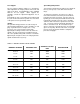
TROUBLE-SHOOTING (3520A Lathe) PROBLEM POSSIBLE CAUSE SOLUTION Excessive vibration. 1. Defective spindle bearings. 2. Worm or defective belt. 3. Defective motor. 4. Workpiece warped, out-of-round, has major flaw, or was improperly prepared for turning. 1. Replace bearings. 2. Replace belt. 3. Replace motor. 4. Correct problem by planing or sawing, or scrap workpiece. Motor or spindle stalls. 1. Excessive cut. 2. Defective motor. 3. Excessive belt wear. 4. Improper belt adjustment. 1.
PARTS LIST: Headstock Assembly (3520A Lathe) No. 1 2 3 4 5 6 7 8 9 10 11 12 13 14 15 16 17 18 19 21 22 23 24 25 26 27 29 30 31 32 33 34 35 36 37 38 39 40 41 42 43 44 45 46 47 48 49 50 51 52 53 55 56 57 18 Part No.
PARTS LIST: Headstock Assembly (3520A Lathe) continued No. Part No. Description Quantity 58 59 60 61 62 63 64 65 66 67 68 69 70 71 72 73 75 76 77 78 79 80 81 82 83 84 85 86 87 6821492 6860800 6294782 3448048 6813062 3601006 3097007 6715015 6294783 6294784 6294785 6294736 6294786 6294787 6294788 6294744 6294789 6294790 6294791 6295733 TS-0640091 TS-1502071 TS-1550031 TS-1540031 6295912 6295913 6295914 6295796 6860802 FWD/REV Switch........................................................................
Headstock Assembly (3520A Lathe) 20
PARTS LIST: Stand & Bed Assembly (3520A Lathe) No. Part No.
Stand & Bed Assembly (3520A Lathe) 22
OPTIONAL ACCESSORIES: Indexer & Bed Extensions (3520A Lathe) No. Part No. Description Quantity 1 2 3 4 5 6294729 3097006 3406005 3585220 6714139 TS-0267021 Indexing Assembly (Items 1 thru 5) Indexing Collar..................................................................................................1 Adjusting Screw Knob .......................................................................................1 Indexing Pin..............................................................................
OPTIONAL ACCESSORIES: Indexer & Bed Extensions (3520A Lathe) 24
OPTIONAL ACCESSORIES: Tool Supports (3520A Lathe) No. Part No. Description 1 2 4 3585011 6294745 6294730 6294731 6294795 6716219 6294740 6294751 6294741 6294739 6294742 Tool Support Pin 5/8 X .495 X 3.50 Ball Bearing Tailstock Center (not shown) 12" Metal Spinning Tool Support Assembly (Items 1 and 4) 26" Tool Support Assembly (Items 6 thru 8) Tool Support Post Socket Head Cap Screw, 3/8-16 x 6-1/4 Bowl Turning Tool Support, R.H. Bowl Turning Tool Support, L.H.
OPTIONAL ACCESSORY: Outboard Turning Stand (3520A Lathe) No. Part No. Description 1 2 3 4 7 8 9 6294732 3042503 6295897 6295898 2695026 3423055 6861700 6769002 Heavy Duty Outboard Turning Stand (Items 1 thru 9) Turning Stand Base Offset Tool Support Pin, 1.00 dia. Offset Tool Support Casting 1.
OPTIONAL ACCESSORIES (3520A Lathe) No. Part No. Description 1 2 3 4 6294736 6294737 6294738 6294744 3" Face Plate, 1-1/4-8 (STD.) 4" Face Plate, 1-1/4-8 (OPT.) 7" Face Plate, 1-1/4-8 (OPT.) Face Plate Wrench OPTIONAL ACCESSORY Part No. Description 6294733 Remote ON/OFF Switch OPTIONAL ACCESSORIES Part No.
ELECTRICAL SCHEMATIC: 3520A Lathe 28
ELECTRICAL: Remote ON/OFF Switch (Optional) NOTE: The lathe can only operate when both the headstock and remote switches are in the "ON" position. STEP 1: Disconnect all electrical power to lathe. STEP 2: Remove the two screws from the control panel. Do NOT disconnect control panel from wiring harness. STEP 3: Run the remote switch's wiring harness through the opening in the back of the headstock and out through the front of the headstock.
ELECTRICAL SCHEMATIC: 3520A Lathe with Remote Switch (Optional) 30
ELECTRICAL SCHEMATIC: 3520A School Lathe (#1352002) 31
ELECTRICAL SCHEMATIC: 3520A School Lathe - 2330009 Kit 32
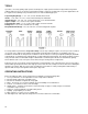
AC INVERTER READINGS: Lathe Speed Chart 33
Instructions for Mounting Indexing Assembly (Optional Accessory) 1. Remove the handwheel. Loosen the two set screws and slide the handwheel off. 2. If your lathe was purchased before January 1998, you must drill a 1/4" hole into the headstock so that the indexer will work properly. Before the 1/4" hole can be drilled you must first make sure that the 1/4" hole will line up with the holes in the indexer.
To order parts or reach our service department, please call our toll-free number between 8:00 a.m. and 4:30 p.m. (CST), Monday through Friday. Having the Model Number and Serial Number of your machine available when you call will allow us to serve you quickly and accurately. Locating the stock number of the part(s) required from your parts manual will also expedite your order. Phone No.: (800) 248-0144 Fax No.
03/03 WMH Tool Group 427 Sanford Rd. LaVergne, TN 37086 Phone:(800) 248-0144 Fax: (800) 274-6840 E-mail: powermatic@wmhtoolgroup.com Website: www.powermatic.