This .pdf document is bookmarked Operating Instructions and Parts Manual Vertical Panel Saw Model 511 shown with optional Adjustable Stop Assembly Powermatic 427 New Sanford Road LaVergne, Tennessee 37086 Ph.: 800-274-6848 www.powermatic.com Part No.
Warranty and service Powermatic warrants every product it sells against manufacturers’ defects. If one of our tools needs service or repair, please contact Technical Service by calling 1-800-274-6846, 8AM to 5PM CST, Monday through Friday. Warranty Period The general warranty lasts for the time period specified in the literature included with your product or on the official Powermatic branded website. • Powermatic products carry a limited warranty which varies in duration based upon the product.
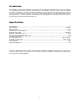
Table of contents Warranty and service ............................................................................................................................................ 2 Warning ................................................................................................................................................................. 4 General Operating Instructions .............................................................................................................................
Warning Read and understand the entire owner’s manual before attempting assembly or operation. Read and understand the warnings posted on the machine and in this manual. Failure to comply with all of these warnings may cause serious injury. Replace the warning labels if they become obscured or removed. This panel saw is designed and intended for use by properly trained and experienced personnel only.
Use the right tool at the correct speed and feed rate. Do not force a tool or attachment to do a job for which it was not designed. The right tool will do the job better and safer. Use recommended accessories; improper accessories may be hazardous. Maintain tools with care. Keep blades sharp and clean for the best and safest performance. Follow instructions for lubricating and changing accessories. Turn off the machine before cleaning.
Familiarize yourself with the location and content of these decals on your machine.
General Operating Instructions The suggestions listed below are meant to give you a general idea of how your new Panel Saw is intended to be operated. No amount of instruction can replace good common sense and experience. Be sure the operators of your new Panel Saw are given enough time and material to become familiar with the general operating characteristics of this machine and have FULLY READ AND UNDERSTAND all general operating and safety instructions. The panel saw is pre-aligned at the factory.
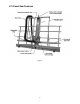
511 Panel Saw Features Figure 2 8
Introduction This manual is provided by Powermatic, covering the safe operation and maintenance procedures for a Model 511 Vertical Panel Saw. This manual contains instructions on installation, safety precautions, general operating procedures, maintenance instructions and parts breakdown. This machine has been designed and constructed to provide years of trouble free operation if used in accordance with instructions set forth in this manual.
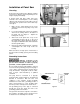
Installation of Panel Saw Uncrating Remove the panel saw from the shipping container and check for damage. Report any damage to the freight company immediately. A wooden block and three cables have been fastened to the counterweight to secure it during shipment. This wooden block and cables must be removed before operation of the saw. Follow steps 1 through 4: 1. Make sure the cable attached to the motor carriage is placed over the pulley on top of the panel saw. 2.
A temporary adapter, shown in Figure 6, can be used to connect a grounded plug to a two-prong outlet. The green rigid ear or lug extending from the adapter must be connected to a permanent ground such as a properly grounded outlet box or receptacle. Simply remove the center screw from the outlet, insert the adapter and re-attach the screw through the grounding ear to the outlet. If in doubt of proper grounding, call a qualified electrician.
2. Feed material through the saw (ripping) or lower the carriage (crosscutting) slowly, smoothly and whenever possible without stopping. Overfeeding can result in poor quality cuts, shorten the life of the blade, and overload the motor. 3. Do not drop heavy material onto the rollers, as this will eventually pound them out of alignment. 4. For best results, place workpiece onto saw with its backside facing the operator. This provides the smoothest cut on the face side of the panel. 5.
6. Start motor and allow it to reach full speed. 7. Pull carriage down slowly and smoothly as the blade moves through the workpiece. Keep one hand on the handle at all times and do not force the saw. NOTE: If the blade binds in the workpiece, or the workpiece shifts during the cut, stop the motor, return the carriage to the top of the guides, restart motor, and then begin the cut again. 8. Support and remove the cut-off piece as the saw completes its cut. 9.
NOTE: If the blade binds in the workpiece, or the workpiece shifts during the cut, stop the motor, back the workpiece out of the saw, reposition workpiece, restart motor, and then begin the cut again. Do not place hands, clothing or body parts under carriage or in cutting path of blade. Do not look directly down line of cut as dust and debris are generated during this operation. 7. As the workpiece passes through the saw, move to the other side and complete the cut by pulling the workpiece past the blade.
Adjusting Crosscut Rulers The panel saw comes with one rip (vertical) ruler and two crosscut (horizontal) rulers. The rip ruler is preset at the factory. The crosscut rulers should be checked and, if necessary, adjusted before operating the saw. Also, they may have to be adjusted after every blade change. With the blade installed, do the following: 1. Remove blade guard. 2. Loosen carriage locking knob and lower carriage down to the rulers. 3.
Step 1: Align Rollers The two outermost rollers are fixed, so adjust all other rollers to them. Place the 6-foot edge of the square across the rollers to check for alignment. The edge of the square should touch all rollers. If it does not, adjust as follows: 1. Clamp the straightedge to the top of the outermost rollers and flat to the frame. Position the clamps above the outermost rollers. 2. Turn each roller to ensure it does not jam or have excessive clearance from the straightedge.
STEP 3: Align Blade Parallel to Guides The blade must move parallel to the guides or tail burning may occur, and the kerf may be wider than the set of the blade. Always adjust the rollers and guides before adjusting the blade. To check for blade alignment: 1. Make sure rollers and guides are aligned first. 2. If the blade “heels”, or leaves burn marks on the cut, move the carriage to a crosscut position and make a test cut.
Do not use cleaning solvents such as gasoline, turpentine, lacquer thinner, paint thinner, or ammonia, as these are harmful to plastic and some of the insulated parts on the machine. Never use flammable or combustible solvents around tools. Do not immerse the saw in liquid as this may create risk of injury, electric shock and damage to the saw. Periodically: 1. The carriage is designed to move smoothly along the guide tubes.
511 Panel Saw – Exploded View I refer to parts list, pages 22-24 19
511 Panel Saw – Exploded View II 20
Parts List: 511 Panel Saw Index No. Part No. Description Size Qty .................. 2078021 .................... Carriage Assembly (Items 15, 17 & 24) ................... ...................................... 1 1 ............... 2218033 .................... Frame Assembly ...................................................... ...................................... 1 2 ............... 2423020 .................... Leg Assembly .......................................................... ..................
Index No. Part No. Description Size Qty 58 .............. 6716218 .................... Hex Head Screw ...................................................... 3/8-16 X 5 ..................... 1 59 .............. 2063181 .................... Motor Bracket Strain Relief Assembly ..................... ...................................... 1 60 .............. 6823020 .................... Indicator Stripe......................................................... ........................... 2 inches 61 ........
511 Panel Saw, Motor with Pushbutton Assembly 2475002 refer to parts list, pages 21-23 23
511 Panel Saw Dust Collection System refer to parts list, pages 21-23 24
Electrical Connections refer to parts list, pages 21-23 25
Parts List: Skilsaw, Model 586, Type 2 (511 Panel Saw) NOTE: For all parts and service on the Skil worm drive motor, contact Skil at 877-754-5999, or www.skiltools.com, to find a Skil service center near you. Index No. Part No. Description Powermatic Part No. 1............... 325089 ............ Bearing Cover 2............... 23331 .............. Washer 3............... 23324 .............. Lock Pin Bushing 5............... 325655 ............ Lock Pin 6............... 44638 .............. “O” Ring1 7..
Index No. Part No. Description Powermatic Part No. 54 .............. 320881 ............ Cord and Plug 55 .............. 5970 ................ Strain Relief 56 .............. 27039 .............. Set Screw (2) 57 .............. 1619X01351 .... Brush and Spring (2) .................... 6861260 58 .............. 306278 ............ Brush Cap (2) .............................. 6861261 59 .............. 315286 ............ Stud3 60 .............. 350005 ............ Plug Button 61 .............. 23334 ......
427 New Sanford Rd. LaVergne, TN 37086 Phone: 800-274-6848 www.powermatic.