This .pdf document is bookmarked Operating Instructions and Parts Manual Mobile Cyclone Dust Collector Model PM2200 For serial # 17090036 and higher Powermatic 427 New Sanford Road LaVergne, Tennessee 37086 Ph.: 800-274-6848 www.powermatic.com Part No.
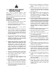
12. Make all machine adjustments or maintenance with the machine unplugged from the power source. 13. Remove adjusting keys and wrenches. Form a habit of checking to see that keys and adjusting wrenches are removed from the machine before turning it on. 1.0 IMPORTANT SAFETY INSTRUCTIONS 14. Keep safety guards in place at all times when the machine is in use. If removed for maintenance purposes, use extreme caution and replace the guards immediately after maintenance is complete.
7. Use proper extension cord. Make sure your extension cord is in good condition. When using an extension cord, use one heavy enough to carry the current your product will draw. An undersized cord will cause a drop in line voltage resulting in loss of power and overheating. Sect. 6.2, Table 2 shows correct size to use depending upon cord length and nameplate ampere rating. If in doubt, use the next heavier gauge. The smaller the gauge number, the heavier the cord. 26.
2.0 Table of contents Section Page 1.0 IMPORTANT SAFETY INSTRUCTIONS ....................................................................................................... 2 2.0 Table of contents ............................................................................................................................................ 4 3.0 About this manual .......................................................................................................................................... 4 4.
4.
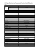
PM22002 Collection drum Capacity Diameter Height Material Main materials Frame Body/housing Paint finish Dimensions Footprint/base dimensions (LxW) Overall dimensions, assembled (LxWxH) Box #1 base machine Shipping dimensions Box #2 frame (LxWxH) Box #3 canister filter Weights Net weight, full kit assembled Net weight Box #1, base machine only Shipping weight Net weight Box #2, frame only Shipping weight Net weight Box #3, canister filter only Shipping weight 1 63 gal. (75.7 L) 24-1/2 in.
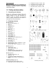
2 8 8 1 Read and understand the entire contents of this manual before attempting assembly or operation. Failure to comply may cause serious injury. Phillips pan hd screw, 1/4x1/2 – HP3 Hex flange hd screw, 5/16x3/4 – HP4 Phillips pan hd screw, M5x8 – HP5 Open end wrench, 10/12mm – HP6 5.0 Setup and assembly 5.1 Unpacking and cleanup Remove all contents from shipping carton and compare to the contents list in this manual. If shipping damage or any part shortages are identified, contact your distributor.
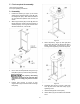
5.3 Tools required for assembly 12mm wrench (provided) Cross-point (Phillips) screwdriver 5.4 Assembly 1. Install fixed casters (Q, Figure 4) and swivel casters (R) to threaded holes in base (B), with hex flange bolts (HP1). Note that fixed casters are mounted below platform side of base, as shown. 2. Attach support frame (SF) to base (B) with hex flange bolts (HP1). Make sure support frame is oriented properly – the long end of lower brace will face toward front, or drum side. Figure 5 5.
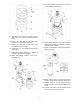
15. Push inlet adaptor (F, Figure 9) onto housing port and tighten with screw (F1). Figure 7 9. Assemble cone (L, Figure 8) to housing (A) and secure with cone clamp (P). Tighten screw on clamp. Figure 9 10. Paste 1-inch wide strip of foam tape (FT1) around cone (L) just above bottom lip. 11. Paste 1-inch wide strip of foam tape (FT1) around flange of drum lid (E). 16. Install canister filter (CF, Figure 10) to housing, aligning the rod finial (CF1) with the slot in the reduction motor platform. 12.
Figure 13 Figure 11 21. Apply 3/4-in. wide strip of foam tape (FT3/4, Figure 12) to lower end of canister filter, just above the lip. 22. Install canister collection bag (T) beneath canister filter and secure with bag clamp (M). Figure 14 6.0 Electrical connections All electrical connections must be done by a qualified electrician in compliance with all local codes and ordinances. Failure to comply may result in serious injury. The PM2200 Dust Collector is rated at single-phase, 230-volt power only.
6.1 GROUNDING INSTRUCTIONS 6.2 Extension cords This appliance must be grounded. If it should malfunction or breakdown, grounding provides a path of least resistance for electric current to reduce the risk of electric shock. This appliance is equipped with a cord having an equipment-grounding conductor and grounding plug. The use of extension cords is discouraged; try to position machines near the power source. If an extension cord is necessary, make sure it is in good condition.
1. Press reset button for 1 second until receiver “beeps” once. 2. Press and hold “ON” button on the remote controller until receiver “beeps” twice. (If you are using multiple remotes, perform step 2 on each remote before proceeding.) 3. Press and hold reset button (C) for 3 seconds until receiver “beeps” 3 times. The remote controller is now ready. Figure 16 7.2 Safety Key The start/stop switch comes equipped with a magnetic safety key. See Figure 16.
8.0 User-maintenance 8.2 Cleaning and bag inspection Turn OFF dust collector and remove plug from power source before performing any adjustments or maintenance. Failure to comply may result in serious injury. 8.3 Motor inspection Empty or replace canister and drum collection bags when full. Make frequent inspections of motor fan, and blow out (with low pressure air hose) or vacuum any accumulation of foreign material to maintain normal motor ventilation. 8.
10.0 Troubleshooting PM2200 Cyclone Dust Collector 10.1 Electrical and motor problems Symptom Possible Cause Correction* Motor will not start. No incoming current. Check connections at plug or circuit panel. Safety key missing from switch. Install safety key. Motor overheated, relay tripped. Low voltage. Allow machine to cool, then press reset button and restart. Check power line for proper voltage. Open circuit in motor or loose connection. Faulty start switch.
10.2 Performance problems Symptom Possible Cause Correction Poor performance; lack of suction. Hose improperly secured at dust origination point. Inlet port is open. Inspect and remedy. Cap unused inlet ports. Collection bag is full. Empty bag (check sight window). Collection drum not sealed properly. Canister filter is dirty. Inspect drum for leaks, make sure lid is tight. Clean filter. Wood has excess moisture content. Use lumber with lower moisture content.
11.1.
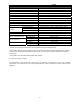
11.1.2 PM2200 Cyclone Dust Collector – Parts List Index No Part No Description Size Qty 1 ................ PM2200-001.............. Motor ....................................................................... 3HP, 230V .................... 1 ................. PM2200-01SC........... Start Capacitor (not shown) ..................................... 250MFD, 250VAC ......... 1 ................. PM2200-01RC .......... Running Capacitor (not shown) ............................... 35F, 400V .................
Index No Part No Description Size Qty 46 .............. JCDC3-33 ................. Swivel Caster ........................................................... 3” ................................... 2 47 .............. JCDC3-33-1 .............. Swivel Caster w/ Brake ............................................ 3” ................................... 2 48 .............. 717531 ...................... Drum Collection Bag (pkg. of 5) .............................. 980 x 1200 /mm ............ 1 49 .............
12.
13.0 Warranty and service Powermatic® warrants every product it sells against manufacturers’ defects. If one of our tools needs service or repair, please contact Technical Service by calling 1-800-274-6846, 8AM to 5PM CST, Monday through Friday. Warranty Period The general warranty lasts for the time period specified in the literature included with your product or on the official Powermatic branded website. Powermatic products carry a limited warranty which varies in duration based upon the product.