
Product Manual


8
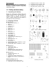
5.3 Tools required for assembly
12mm wrench (provided)
Cross-point (Phillips) screwdriver
5.4 Assembly
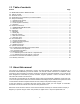
1. Install fixed casters (Q, Figure 4) and swivel
casters (R) to threaded holes in base (B), with
hex flange bolts (HP1). Note that fixed casters
are mounted below platform side of base, as
shown.
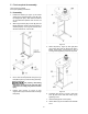
2. Attach support frame (SF) to base (B) with hex
flange bolts (HP1). Make sure support frame is
oriented properly – the long end of lower brace
will face toward front, or drum side.
Figure 4
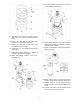
3. Use a hoist with straps/hooks through the eye
bolts (EB, Figure 5) to raise housing assembly.
Use properly rated lifting
equipment connected to the eye bolts atop
unit. Failure to comply may result in serious
injury.
4. Position main housing (A, Figure 5) onto
support frame (SF) and secure with hex flange
bolts (HP1).
Figure 5
5. Attach left panel (I, Figure 6), and right panel
(H) to frame (SF) with hex flange bolts (HP1).
NOTE: Feed switch cords through to top of
housing before tightening screws on left panel.
Figure 6
6. Assemble upper drum (C, Figure 7) and lower
drum (D) and secure with drum clamp (X) by
tightening screw.
7. Install handle (N) with screws (HP3).
8. Install casters (S) into threaded holes beneath
drum.