
Product Manual


9
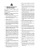
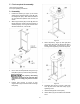
Figure 7
9. Assemble cone (L, Figure 8) to housing (A) and
secure with cone clamp (P). Tighten screw on
clamp.
10. Paste 1-inch wide strip of foam tape (FT1)
around cone (L) just above bottom lip.
11. Paste 1-inch wide strip of foam tape (FT1)
around flange of drum lid (E).
12. Install hose (J) to cone and drum lid with hose
clamps (K).
13. Install quick-release handle (G) to flanges of
cone with pan head screws (HP5).
14. Attach quick-release handle to drum lid (E)
using nuts (E
1
).
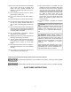
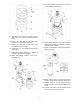
Figure 8
15. Push inlet adaptor (F, Figure 9) onto housing
port and tighten with screw (F
1
).
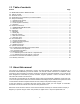
Figure 9
16. Install canister filter (CF, Figure 10) to housing,
aligning the rod finial (CF
1
) with the slot in the
reduction motor platform.
17. Tighten canister filter to housing using eight hex
flange bolts (HP4).
Figure 10
18. Mount hoses (V, Figure 11) to the two ports on
housing (A) and secure with hose clamps (W).
19. Position hoses (V) in hose hangers (Y) and
secure hangers to frame with pan head screws
(HP2).
20. Connect main motor cord and reduction motor
cord, as shown in Figure 11 insets.