This .pdf document is bookmarked Operating Instructions and Parts Manual Deluxe Bench-top Mortiser Model: 701 Shown with optional chisel/bit sets For serial no. 18077010001 and higher Powermatic 427 New Sanford Road LaVergne, Tennessee 37086 Ph.: 800-274-6848 www.powermatic.com Part No.
Warranty and Service Powermatic® warrants every product it sells against manufacturers’ defects. If one of our tools needs service or repair, please contact Technical Service by calling 1-800-274-6846, 8AM to 5PM CST, Monday through Friday. Warranty Period The general warranty lasts for the time period specified in the literature included with your product or on the official Powermatic branded website. Powermatic products carry a limited warranty which varies in duration based upon the product.
Table of Contents Warranty and Service.................................................................................................................................... 2 Table of Contents .......................................................................................................................................... 3 Warnings ....................................................................................................................................................... 4 Introduction ....
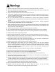
Warnings 1. Read and understand the entire owner's manual before attempting assembly or operation. 2. Read and understand the warnings posted on the machine and in this manual. Failure to comply with any of these warnings may cause serious injury. 3. Replace the warning labels if they become obscured or removed. 4. This mortiser is designed and intended for use by properly trained and experienced personnel only.
26. Make sure the work piece is securely attached or clamped to the table. Never use your hand to hold the work piece. 27. Turn off the machine before cleaning. Use a brush or compressed air to remove chips or debris — do not use your hands. 28. Do not stand on the machine. Serious injury could occur if the machine tips over. 29. Never leave the machine running unattended. Turn the power off and do not leave the machine until it comes to a complete stop. 30.
Introduction This manual is provided by Powermatic covering the safe operation and maintenance procedures for a Model 701 Deluxe Bench-top Mortiser. This manual contains instructions on installation, safety precautions, general operating procedures, maintenance instructions and parts breakdown. This machine has been designed and constructed to provide consistent, long-term operation if used in accordance with instructions set forth in this manual.
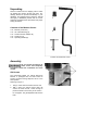
Unpacking Remove contents from the shipping carton. Check for damage and ensure all parts are intact. Any damage should be reported immediately to your distributor and shipping agent. Read the manual thoroughly to familiarize yourself with the correct assembly and maintenance procedures and proper safety precautions.
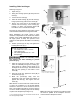
Operating Handle Referring to Figure 2: The operating handle can be mounted on either the left- or right-hand side of the mortiser. The handle hub (D) comes mounted on the right-hand side from the factory. If right-hand operation is desired skip steps 1–3 and proceed to step 4. For left-hand operation the hub must be moved to the left side as follows: 1. Unscrew and remove the hub lock knob (A), flat washer (B), spring (C) and hub (D) from the pinion shaft (E). 2.
Overview – Chuck Extension Do you need it The 701 Mortiser comes with the chuck already assembled at the factory, intended to be used with augers having long shanks. Augers come with long or short shanks (Figure 4) depending on the manufacturer. Long shank augers If you plan to install an auger with a long shank, you can skip this section and proceed to the Installing Chisel and Auger section on page 10.
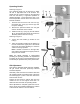
Installing Chisel and Auger Referring to Figure 6: 1. Open door (A). 2. Swing two bushing spacers (B) away from the head (C). 3. Loosen the lock screw (D). 4. Insert the chisel bushing* (E) into the head (C), lining up the hole (F) with the lock screw (D). 5. Set the lock screw (D) so the threaded end extends into the hole (F) of the bushing (E), holding it in place. The bushing should still have about 1/4" of vertical travel margin.
Securing Mortiser to Work Bench It is highly recommended to secure the mortiser to the workbench to prevent the possibility of tipping, sliding or "walking" during operation. Secure the mortiser to the bench with fasteners (not supplied) through four holes located in the base (Figure 7). Tool Holder Referring to Figure 8: The 701 Bench-top Mortiser has a tool holder (A) that is installed at the factory and requires no assembly.
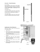
Grounding Instructions This machine must be grounded while in use to protect the user from shock In the event of a malfunction or breakdown, grounding provides a path of least resistance for electric current to reduce the risk of electric shock. If you are not sure whether your outlet is properly grounded, consult a qualified electrician. Referring to Figure 9: As received from the factory, your mortiser is ready to run at 115-volt operation.
Chisel Parallel to Workpiece Referring to Figure 12: The chisel can be adjusted parallel to the workpiece as follows: 1. Loosen the two clamps (A) that secure the fence (B). 2. With the adjust knob (C), move the fence back far enough to insert the workpiece (D) between the chisel (F) and fence (B). Raise the workpiece hold-down clamp (E) if necessary. 3. With the operating handle (G) bring the head down until the chisel points are almost at the table level. 4.
Fence and Clamp Referring to Figure 13: The 701 Mortiser is equipped with a forward/backward movement adjustable fence (B) and hold-down clamp (F, K, L) for securing the workpiece during mortising operations. Fence Adjustment To adjust the fence (B) forward or backward: 1. Loosen two clamps (A) that lock the fence. 2. Turn the knob (C) and adjust the fence (B) forward or backward (D) to the desired position. 3. Lock the clamps (A). Hold-down Clamp There are two ways that the hold-down clamp can be used.
Operation 1. Set the depth stop to the required depth of cut (refer to the Depth Stop Adjustment section on page 12). 2. Place workpiece on table and against the fence. 3. Adjust the fence until the workpiece is in the correct position (see the Fence and Clamp section on page 14). 4. Clamp the workpiece or set the clamp to the desired height as described in the Fence and Clamp section on page 14) Before turning the machine on, verify that the chuck key is not in the chuck. 5.
Maintenance Before any intervention on the machine, disconnect it from the electrical supply by pulling out the plug or switching off the main switch! Failure to comply may cause serious injury. General A coat of paste wax applied to the table and column will help to keep the surfaces clean. Figure 16 If the power cord is worn, cut, or damaged in any way, have it replaced immediately.
701 Mortiser Assembly Drawing Patent No.
701 Mortiser Parts List Index No. Part No. Description Size Qty 1 ............... 701-164MA .............. Motor Assembly (includes #1.1 thru 1.10) ........... .................................... 1 1.1 ............ 701-164M ................. Motor……………………………………..3/4HP, 115/230V, 1PH, 60HZ ..... 1 1.2 ............ 994534 ..................... Switch................................................................... .................................... 1 1.3 ............ 701-165B .................
Index No. Part No. Description Size Qty 51 ............. 701-136B ................. Column ................................................................. .................................... 1 52 ............. TS-1504061 ............. Socket Hd Cap Screw .......................................... M8-1.25 x 30L ............. 4 53 ............. TS-1551061 ............. Lock Washer ........................................................ M8 ............................... 4 54 ............. TS-1550061 .
Wiring Diagram for 701 Mortiser 230V 115V Optional Accessories Optional accessories can be purchased by calling the service department at the number below. 1791312 701-RB Riser Block Kit Ordering Replacement Parts Replacement parts are listed on the following pages. To order parts or reach our service department, call 1-800-274-6848 Monday through Friday, 8:00 a.m. to 5:00 p.m. CST.
Dimensions for 701 with premium chisels mounted (Chisel and bit sets purchased separately) Powermatic 701 Mortiser with Premium Chisels 1791091 1/4” chisel1 1791092 5/16” chisel 1791093 3/8” chisel 1791094 1/2” chisel 1791095 3/4” chisel A Total Chisel Length (installed) 3-21/32” 3-7/8 3-7/8” 3-7/8” 5-13/16” B Useful Chisel Plunge 1-13/16” 2-1/8” 2-3/4” 3-5/32” 5” C Maximum Chisel Centerline to Fence 4-3/8” 4-3/8” 4-3/8” 4-3/8” 4-3/8” D Maximum Working Clearance2 4-29/32” 4-11
This page intentionally left blank.
This page intentionally left blank.
427 New Sanford Road LaVergne, Tennessee 37086 Phone: 800-274-6848 www.powermatic.