
Product Manual
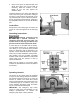
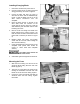

Table Of Contents
- Straight Line Rip Saw
- IMPORTANT SAFETY INSTRUCTIONS
- Table of Contents
- Specifications
- Features
- Receiving
- Installation
- Adjustments
- Operation
- Maintenance
- Optional Accessory
- Troubleshooting
- Replacement Parts
- Parts List: Infeed Body Assembly
- Infeed Body Assembly
- Parts List: Arbor Spindle Assembly
- Arbor Spindle Assembly
- Parts List: Motor and Drive Unit Assembly
- Motor and Drive Unit Assembly
- Parts List: Laser Assembly (Optional Accessory)
- Parts List: Roller and Frame Assembly
- Roller and Frame Assembly
- Table and Stand Assembly
- Parts List: Electrical Control Panel (SLR12-443)
- Electrical Connections
- Preventive Maintenance
- Warranty and Service

10
Adjustments
Main Belt Tension
1. Disconnect machine from power source.
2. Open back panels to expose the motor,
pulleys and belts, as shown in Figure 10.
Loosen hex nut (Fig. 11) and turn the
adjustment screw as needed to adjust the
tension. Proper tension is achieved when
there is a small amount of deflection by
using moderate finger pressure on the belt
midway between the pulleys.
3. Tighten hex nut (Fig. 11) and replace
panels.
Gearbox Belt Tension
1. Disconnect machine from power source.
2. Open lower back panel and loosen nuts on
the motor base (Fig. 12). Adjust motor base
up or down as needed, then tighten nuts.
Proper tension is achieved when there is a
small amount of deflection by using finger
pressure on the belt midway between the
pulleys.
3. Replace panels.
Figure 10
Figure 11
Figure 12